
Oct 18, 2026Precision Engineering & Tooling
Fuel Vapor Canister Housing Mold Design
Real PA66 automotive canister housing mold project: four-point hot runner, filling trials, sealing-interface design, warpage risks, and dimensional control.
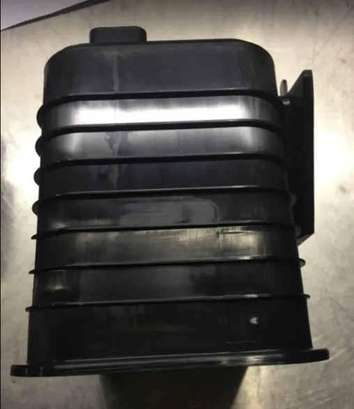
For an automotive fuel vapor canister housing, successful injection molding is not simply a matter of filling a large plastic cavity. The molded shell must maintain its intended geometry at mounting locations, openings, joining interfaces, and other function-critical features. Tooling decisions that appear minor during DFM—such as gate distribution, local wall transitions, parting-line placement, or ejection support—can influence later assembly and dimensional repeatability.
An earlier JST Mould automotive housing project offers a practical engineering reference. The project documentation identifies a black PA66 housing with nominal recorded dimensions of approximately 198 × 172 × 149 mm, a four-point hot-runner feeding arrangement, and hardened 1.2343 tooling steel. The available project photographs show the mold installed on a molding machine, progressive filling samples, and trial-part weighing. These records document real tooling and trial activity; they do not, by themselves, establish a specific leakage rate, warpage tolerance, production yield, or final approval status.
This article uses those records to explain the decisions that matter when designing an injection mold for a fuel vapor canister housing—and what an automotive buyer should verify before committing to tooling.
1. Start With the Housing’s Functional Interfaces
An EVAP canister housing is part of an assembly, not an isolated molded shape. Its interfaces may include a perimeter joining feature, ports, mounting flanges, attachment points, and locating geometry. The precise interface requirements depend on the assembly design, and the molded housing alone should not be assumed to provide the complete system seal.
Before tooling design, distinguish three different engineering concerns:
- A functional sealing interface on the molded component must meet the relevant mating, welding, gasket, or joining requirements specified by the customer.
- A mold shut-off surface is where tooling components meet to contain the melt and control flash. It is not automatically the same as the finished part’s seal.
- A weld line in the molded plastic is a region where melt fronts meet; it is not the same as an assembly weld or welded joint.
That distinction helps prevent a common DFM mistake: optimizing only the visible outside surfaces while overlooking the parts of the geometry that actually locate, join, or seal the assembly.
Actual automotive fuel vapor canister housing side view, showing molded ribs and the overall shell profile. Image details are selectively obscured for confidentiality.
2. Wall Thickness, Ribs, and Dimensional Stability
A housing with deep walls, external ribs, and a peripheral flange can develop uneven shrinkage if its sections are not designed and packed consistently. Thick transitions near mounting features can cool differently from broad thin walls. Rib intersections may increase local mass and contribute to sink or distortion, while abrupt changes in wall thickness can affect flow and pressure transmission.
The design review should therefore inspect nominal wall distribution, rib-to-wall transitions, bosses and mounting structures where present, and the continuity of the flange or joining region. The purpose is not to apply one universal rib ratio to every geometry. It is to identify the actual critical-to-function regions and assess whether the mold and molding process can reproduce them reliably.
Material selection is part of this review. The archived project sheet identifies customer-supplied black PA66. If the specified grade is glass-fiber reinforced, orientation-dependent shrinkage, weld-line properties, and differential distortion deserve additional attention. Fiber content and direction-specific shrinkage values must come from the confirmed grade and supplier data rather than from assumptions about PA66 in general.
3. What a Four-Point Hot Runner Changes
The project record specifies a four-point hot-runner feeding concept. Multiple gates can reduce the flow distance from each feed point and provide options for packing a large, complex cavity. They also create engineering questions: Do the melt fronts advance at comparable rates? Where do they meet? Could the meeting regions affect a functional interface? Is one area being overpacked while another remains difficult to fill?
A four-point arrangement is therefore a design choice to validate—not proof of balanced filling by itself. The review should consider the position of the gate entrances, the flow lengths into different wall regions, local material temperature, and the response of the part through transfer and packing. Hot-runner settings and gate behavior also need to remain repeatable between trials.
Short-shot or progressive filling studies are useful because they reveal the sequence in which the cavity fills. A photographed incomplete sample can help engineers ask where flow fronts travel and which regions may be last to fill. It cannot alone establish the precise location or strength of every weld line, or prove that a vent is adequate.
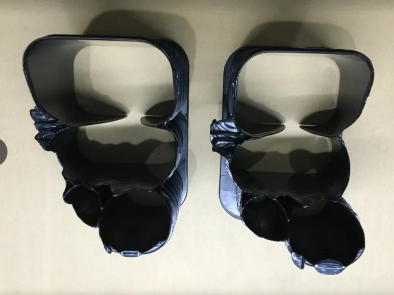
Actual trial-stage partial-fill samples from the fuel vapor canister housing project, used to review filling progression in the four-point hot-runner concept.
For a broader explanation of simulation-led gate and filling decisions, see How Moldflow Analysis Reduces Injection Mold Risk Before Steel Cutting.
4. Weld Lines, Air Traps, and Venting
Where melt fronts converge, the process may create weld lines. In areas with narrow passages, ribs, or deep flow paths, trapped air can further complicate filling. The risk to the part depends on the resin grade, local temperature and pressure, geometry, and whether the affected location is structural, cosmetic, or function-critical.
During DFM and mold review, the practical questions include:
- Are predicted melt-front meeting points close to a critical sealing or joining surface?
- Where is air most likely to be displaced at end of fill?
- Can parting-line vents, insert clearances, or other engineered vent paths release that air without unacceptable flash?
- Can the chosen gates and process window produce repeatable filling without hiding a venting problem through excessive pressure?
The venting design must be established against the actual material and mold geometry. Specific vent depths should not be inferred from photographs. For further background, see Injection Mold Venting Design: Vent Depth, Burn Marks and Short Shots.
5. Parting Line, Flash Control, and Sealing Features
For an automotive housing, the parting-line strategy should be evaluated together with the location of the peripheral flange, openings, and mating features. Flash on a function-critical interface may interfere with assembly or a specified seal, while mismatch at a shut-off can alter the shape of a molded edge.
The correct objective is not to insist that every joining surface must be entirely free from a parting line. Instead, engineering should define the allowable flash, mismatch, surface condition, and geometric tolerance for each critical interface. Those requirements then guide part orientation, shut-off construction, steel fitting, and inspection planning.
Any assertion that a molded housing is leak-tight requires the customer-defined assembly and test method. A visually clean mold trial sample is not a substitute for a validated leakage or pressure test.
6. Shrinkage, Cooling, and Warpage Control
Warpage can result from several interacting causes: thickness variation, asymmetric stiffness, uneven temperature distribution, packing differences, mold constraints, material orientation, and the timing of release. For a housing with relatively tall walls and peripheral features, even modest deformation may influence mounting alignment or assembly fit.
The original project sheet records a 1.20% shrinkage design value. This is a historical tooling-design input, not a verified measurement for every direction or every PA66 formulation. If the customer-selected material is fiber reinforced, the final review must consider the grade's directional behavior rather than treating one nominal percentage as an exact predictor of finished dimensions.
A practical warpage review should connect part geometry with gate locations, cooling layout, packing conditions, and actual measurements after thermal stabilization. Where a deviation is observed, the next step is to identify its cause. Changing cavity steel before distinguishing material behavior from process instability can create an unnecessary second correction.
For related material and geometry considerations, read Automotive Structural Thermoplastics in Injection Molding: Tooling, Warpage and Material Challenges.
7. Ejection and Mold-Trial Checks
A filled housing can still distort during demolding. Ribbed and deep-wall regions may retain the core as they shrink, while uneven ejection support can load thin walls or change a flange profile. The mold design therefore needs appropriate draft, stable support, and an ejection concept suitable for the actual release forces and critical surfaces.
The project’s machine photograph confirms that the tooling progressed to an on-machine trial stage. It does not establish which trial iteration was photographed or demonstrate an approved mass-production cycle. The value of the image is to connect the engineering discussion to a real trial setting rather than an assumed process outcome.
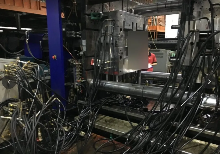
Actual injection mold installed for trial molding of the automotive fuel vapor canister housing.
A useful trial sequence should review incomplete-fill behavior, flash, weld-line locations, demolding marks, local deformation, and dimensions measured on samples produced under stable conditions. For the principles behind that process, see Scientific Injection Molding (SIM) for T1 Mold Trials: A Practical Validation Guide (Part 1).
8. From Trial Samples to Repeatable Production
Trial sample weight can be one useful process observation, especially when reviewing filling progression or shot-to-shot consistency. However, weight on its own does not prove dimensional conformity or sealing performance. It matters whether the sample is a short shot or a complete part, whether any runner or attached material is included, and whether the weighing conditions are comparable.
The archived trial photograph shows two molded samples on a weighing scale. Because the photograph does not independently establish the measurement units, sample condition, or an approved target weight, no numerical part-weight claim is made here.
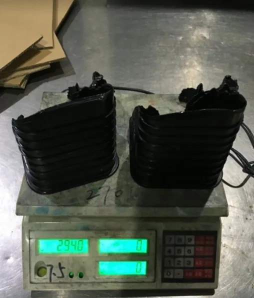
Actual trial-stage housing samples on a weighing scale; weight checks are one input to filling and process review, not standalone proof of part acceptance.
Before moving from a successful trial to sustained supply, automotive projects normally require an agreed inspection plan for critical dimensions and interfaces, plus repeatability evidence appropriate to the customer's requirements. Mold acceptance and production-part approval are separate decisions; neither should be implied solely by photographs of molded parts.
9. What to Include in a Fuel Vapor Canister Housing Mold RFQ
A better RFQ allows the moldmaker to assess sealing-interface, distortion, and production risks before quoting a steel concept. For this category of part, the most useful inputs are:
- 3D CAD geometry and, where available, a dimensioned 2D drawing;
- confirmed polymer grade, filler content, and supplier data sheet;
- critical joining/sealing interfaces and customer-defined functional requirements;
- important dimensional tolerances, datum references, and inspection expectations;
- estimated annual volume, production location, and molding-machine constraints;
- requirements for appearance, traceability, trial samples, and mold validation.
Where the design is confidential, these materials can be exchanged under an appropriate NDA. The objective is to connect RFQ pricing with the actual engineering and quality requirements, not to quote a complex functional housing from a photograph alone.
FAQ
Is PA66 suitable for an automotive fuel vapor canister housing?
PA66 may be specified for certain housing designs, but suitability depends on the exact grade, fuel-vapor exposure, operating temperature, dimensional requirements, assembly method, and customer validation. The historical project record identifies PA66; it does not replace application-specific material approval.
Why use four hot-runner gates for a large housing?
Multiple feed points can help manage flow lengths and packing access in a complex geometry. The correct number and locations still require engineering review because multi-point filling can create melt-front meeting regions and packing imbalance.
Does a visible weld line mean the housing will leak?
Not necessarily. A molded weld line and an assembly sealing joint are different features. The consequences depend on the exact line location, material, interface design, and relevant functional testing.
How can glass fiber affect housing warpage?
In a confirmed glass-filled polymer grade, fiber orientation can produce directional shrinkage and influence distortion. The effect must be assessed using the actual grade, gate arrangement, geometry, simulation where appropriate, and measured trial samples.
Can short-shot samples replace Moldflow analysis?
No. They provide physical evidence of filling progression under specific trial conditions. Simulation can help evaluate design scenarios earlier, while short-shot studies and dimensional inspection provide different forms of real-world validation.
What is needed before approving a fuel vapor canister housing mold?
The customer and moldmaker should agree on the relevant mold trial, dimensional, interface, material, process, and functional acceptance criteria. A successful fill study or a visually acceptable sample alone is insufficient.
Request a DFM and Injection Mold Quotation
Developing an automotive fuel vapor canister housing or another functional PA66 enclosure? JST Mould can review your 3D CAD, critical interfaces, material requirements, and production targets to discuss mold feasibility, gate strategy, potential warpage risks, and a suitable tooling quotation.