
Jul 6, 2026Precision Engineering & Tooling
Scientific Injection Molding (SIM) Protocol 2026: The Data-Driven Roadmap to T1 Success (Part 1)
2026 SIM protocol for Tier-1 molds. Mastering viscosity curves, gate freeze, and Reynolds number cooling for stable Tier-1 mass production.
I. The True Purpose of Mold Trial
- Verify whether the mold structure design is scientific and reasonable, assess the quality of mold processing, and confirm the feasibility of injection molding.
- Identify problems in the mold structure and processing (including filling balance, ejection performance, cooling efficiency, venting effectiveness, injection difficulty, part quality, and required manpower). Propose specific measures to modify the mold.
- Establish reasonable standard injection molding process parameters and customer-approved part quality standards (approved sample parts). This ensures smooth mass production, reduces material waste and defect rates, improves efficiency, and minimizes machine and labor requirements.
II. Scientific Mold Trial Process
- Receive mold trial request
- Mold trial preparation
- Install the mold
- Heat up the mold temperature
- Relevant personnel on site
- Mold dry run inspection
- Set process parameters
- Produce trial samples
- Inspect appearance
- Mark samples
- Weigh parts
- Inspect dimensions
- Perform assembly and functional testing
- Write mold trial report
CASE STUDY --This is the molding have the successful trial run in customer side.
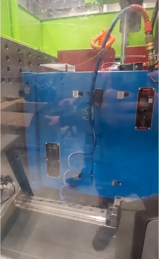
Preparation Phase: Ensuring safe handling and alignment before the 2026 SIM protocol begins.
III. Preparation Work Before Mold Trial
- Preparation of plastic raw materials (including regrind and proper drying).
- Selection of injection molding machine type and size.
- Clear understanding of mold trial requirements and objectives.
- Determination of mold trial steps and methods.
- Thorough understanding of the mold structure and action sequence.
- Review of the plastic material's processing properties (refer to the material data sheet).
IV. Preparation of Mold Trial Tools
(1) Contact or infrared mold temperature measuring instruments.
(2) Cameras and video recorders.
(3) Vernier calipers, micrometers, feeler gauges, measuring fixtures, and jigs.
(4) Electronic scale and dedicated mold inspection lighting.
(5) Basic mold repair tools (sandpaper, lubricant, oil stones, wrenches, files, etc.). 8. Drawings and Records(1) Product drawings and mold drawings.
(2) Oil-based pens for marking plastic parts.
(3) Molding condition record sheets.
(4) Related assembly components and spare parts.
V. How to Correctly Select an Injection Molding Machine for Mold Trial
- Clamping Force Determination Calculate the projected area of the injection molded part, estimate the required clamping force, and select an appropriate machine.
- Shot Weight Determination Calculate the weight of one shot (including all cavities). Ensure the machine's maximum shot capacity is sufficient. Select a machine where the shot weight is 30%-85% of the machine's maximum shot capacity.
- Confirmation of mold size compatibility and mold opening stroke.
- Check whether the injection machine nozzle tip radius and orifice diameter match the mold (and ensure concentricity).
- Other requirements (hydraulic core-pulling function, unscrewing function, etc.).
- Preferably select a machine consistent (or close) to the one used in actual production.
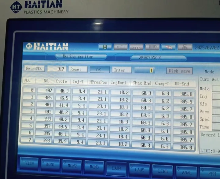
Data Acquisition: Monitoring cycle-to-cycle consistency via scientific molding screens.
VI. How to Use Raw Materials for Mold Trial
- Use the same grade of raw material as in mass production whenever possible.
- Maintain the same regrind (runner scrap) addition ratio as in production.
- Use properly dried raw materials.
- Select materials based on the specific objectives of the mold trial.
- Use materials according to customer and product requirements.
VII. Eight Major Aspects of New Mold Trial(I) Mold Dry Run Test – Verify Mold Actions
A. Low-pressure mold opening and closing inspection
- Perform opening and closing at slow, medium, and fast speeds three times each. Check for abnormal noises or sticking during movement.
- Ensure smooth mold actions with no interference.
B. Ejection system inspection (under low pressure)
- Perform ejection at slow, medium, and fast speeds three times each. Check for abnormalities.
- After ejection, check if ejector pins or sleeves on flat surfaces loosen or stick.
- For angled ejector pins or sleeves, confirm positioning pins are installed (to prevent loosening or rotation).
- Check for abnormal noises or vibration during ejection.
C. Mold reset inspection
- Perform reset at slow, medium, and fast speeds three times each. Verify full return to position.
- After reset, angled ejector pin end faces should not protrude more than 0.1 mm above the core or be flush with it.
- Ensure good contact of reset limit switches.
- Confirm no interference between ejector pins and slides during ejection (slides must return fully).
- Check if the mold has a mechanical ejector reset mechanism.
D. Slide (core-pulling) action inspection
- Perform opening and closing at slow, medium, and fast speeds three times each. Observe smooth slide movement.
- Verify normal slide return and no interference with ejector pins.
- Ensure reliable slide locking.
- Check the sequence of hydraulic core-pulling actions.
- Confirm no scratching or sticking of slides during dry run.
(II) Filling Balance Test
- Produce 5 consecutive shots and weigh them.
- Record the individual part weight for each cavity in every shot.
- Reduce injection volume and produce 3 shots each at approximately 20%, 50%, and 90% fill.
- Weigh and record the weight of each part.
- If the weight difference between the heaviest and lightest parts is less than 2%, the filling is considered balanced. Otherwise, filling is unbalanced.
- For single-cavity molds, perform filling balance observation by monitoring actual flow behavior.
(III) Packing Time (Gate Freeze) Test
- Set packing time to 1 second initially and mold 3 shots.
- Increase packing time incrementally while reducing cooling time to keep the overall cycle time constant, until the gate freezes and part weight no longer increases.
- Record part weights at different packing times in a table.
- Determine the optimal packing time from the data and graph.
(IV) Optimal Clamping Force Determination
- With optimal switchover position and packing pressure set, start at 90% of maximum clamping force. Mold 3 shots and record weights.
- Reduce clamping force by 5 tons each time, mold 3 shots, and record weights until part weight suddenly increases by about 5% and flash appears around the part.
(V) Optimal Cooling Time Determination
- With suitable injection conditions (parts fully packed), start with a longer cooling time to ensure complete cooling. Mold 3 shots and measure dimensions.
- Record dimensions and observe part deformation.
- Reduce cooling time by 1 second each step and mold 3 shots.
- Continue until parts begin to deform or dimensions start to shrink.
- Measure dimensions only after parts have fully cooled (approximately 15 minutes).
- Determine optimal cooling time based on part dimensional stability.
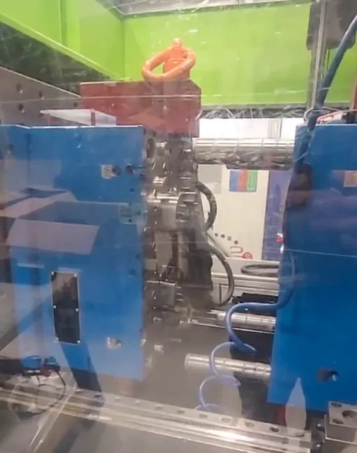
Thermal Management: Calculating Reynolds numbers to ensure turbulent flow and stable Delta-T.
General Empirical Cooling Time Formulas
- For mold temperature ≤ 60°C: Cooling time ≥ t(1 + 3t)
- For mold temperature > 60°C: Cooling time ≥ 1.5t(1 + 3t) (where t = maximum wall thickness of the part)
Theoretical Cooling Time Formula
s = 2T² Log₄[(T_c - T_m) / (T_k - T_m)] / A
(where s = minimum cooling time, T = part thickness, A = thermal diffusivity of the material, T_k = ejection temperature, T_m = mold temperature, T_c = melt temperature)
Note: JST uses these theoretical baselines to cross-verify real-world sensor data during T1 trials.
(VI) Cooling Water Flow Status Test
- Measure data using pressure and flow meters and record in the table.
- Measure and record cooling channel diameters.
- Determine kinematic viscosity based on cooling water temperature.
- Calculate Reynolds number (Re) using the formula: Re = 3160 × (cooling water flow rate) / (cooling channel diameter × kinematic viscosity)
- Turbulent flow provides better cooling (Re < 2000 = laminar; Re > 4000 = turbulent; Re 2000–4000 = transitional).
(VII) Mold Cooling Uniformity Test
- Use a mold temperature measuring instrument to check 10 points each on the core and cavity. Record temperatures.
- The actual temperature at each point should differ from the average by less than 2°C. If not, the cooling system needs improvement.
(VIII) Melt Viscosity Analysis – Determine Optimal Injection Speed
- Record hydraulic oil temperature, melt temperature, and mold temperature.
- Set the screw cushion position and use single-stage injection only.
- Set packing pressure and time to zero. After determining the starting position, gradually increase injection speed.
- Adjust speed to fill approximately 95% of the part (maintain 5–10 mm cushion).
- Record the maximum injection speed achieved at 95% fill.
- Record peak injection pressure at this speed in the injection speed analysis table.
- Gradually reduce injection speed and increase pressure. Record peak pressures at 95% fill.
VIII. Mold Trial Work Content
- Identify issues in the injection mold (ejection performance, cooling efficiency, injection difficulty, part quality, manpower requirements, etc.). Propose mold modification measures and prepare a detailed mold trial report.
- Produce sample parts and submit them to the customer for approval and signing of OK samples.
- Establish reasonable injection molding process parameters to guide production setup.
- Determine injection cycle time, daily output, material consumption, defect rate, and machine-side manpower.
- Fabricate measuring and correction fixtures/jigs for production use.
- Develop product quality standards per customer requirements and provide limit samples to the quality control and injection departments.
- Label and archive the injection mold with complete records.
- Prepare product packaging documentation (BOM list) for the purchasing department.
- Compile "Injection Molding Production Work Instructions" to guide operators.
IX. Method for Initial Setting of Mold Trial Process Conditions
- Start without packing pressure; use single-stage injection only.
- Set melt temperature slightly lower (to prevent degradation) and mold temperature slightly higher.
- Start injection pressure and back pressure from lower values (to avoid over-packing or material overheating).
- Start with higher clamping force (to prevent flash).
- Begin with a slightly slower injection speed (to protect the mold) and lower metering stroke (to avoid over-filling).
- Start with longer injection time (to confirm gate seal).
- Once parts are fully packed, enable packing and adjust packing pressure and time from low to high.
X. Regulations on Number of Mold Trials for New Molds
New molds are generally limited to a maximum of 3 trials. The purposes are:
- Force product and mold design engineers to optimize structures and improve design quality.
- Enhance responsibility and work quality among mold designers, machinists, follow-up engineers, and trial personnel.
- Encourage optimization of process parameters and higher trial quality.
- Reduce waste of materials, labor, time, and energy, thereby lowering trial costs.
- Shorten new product development cycles, satisfy customers, and strengthen competitiveness.
XI. Methods to Reduce the Number of Mold Trials
- "Do it right the first time." Product design engineers should communicate closely with customers to fully understand requirements and minimize design changes that cause additional modifications or trials.
- Organize a "mold design requirements meeting" with relevant departments to complete DFM (Design for Manufacturability) for customer approval and avoid design errors.
- Use Moldflow analysis software to optimize mold structure, runners, gates, cooling, venting, and ejection.
- Provide professional injection molding training to trial personnel to improve their ability to identify, analyze, and solve problems.
- Strictly follow scientific mold trial methods and procedures.
- Prepare 10% more samples than requested to accommodate any sudden customer needs.
XII. Measures to Shorten Mold Trial Time
- Assign experienced, knowledgeable, and responsible personnel to perform trials (clear qualification requirements).
- Trial personnel must carefully read the trial request and fully understand objectives and requirements.
- Complete all pre-trial preparations in advance.
- Improve mold design and machining quality to reduce setup time.
- Ensure engineering and mold manufacturing personnel are present on site to observe results and address issues promptly.
- Have follow-up personnel monitor sample results in real time to reduce waiting.
- Set time limits for each trial and standardize the process to drive higher efficiency.
- Provide professional injection molding training to enhance problem analysis and resolution capabilities.
XIII. Ten Major Mold Aspects to Review During Mold TrialI. Gate Location, Type, Size, and Quantity Review A. Gate Location Review
- Is the gate located at the thickest wall section of the part?
- Does the gate location affect melt flow capability (flow length ratio check)?
- Does it facilitate proper venting?
- Does it avoid direct impingement on inserts (to prevent displacement)?
- Is it away from high-stress areas (to prevent stress cracking)?
- Does it ensure balanced filling in single-cavity molds?
- Does it avoid shooting directly into empty cavities (causing snake-like flow marks)?
- Are weld lines positioned away from high-stress areas?
- For multi-cavity molds, does gate location cause unbalanced clamping forces?
- Does gate location affect part shrinkage and warpage?
- Does it support effective packing (to avoid sinks or voids)?
- Is the gate easy to process and remove?
- Does gate removal affect part appearance?
- For pin-point gates, is the remaining gate vestige length and height appropriate?
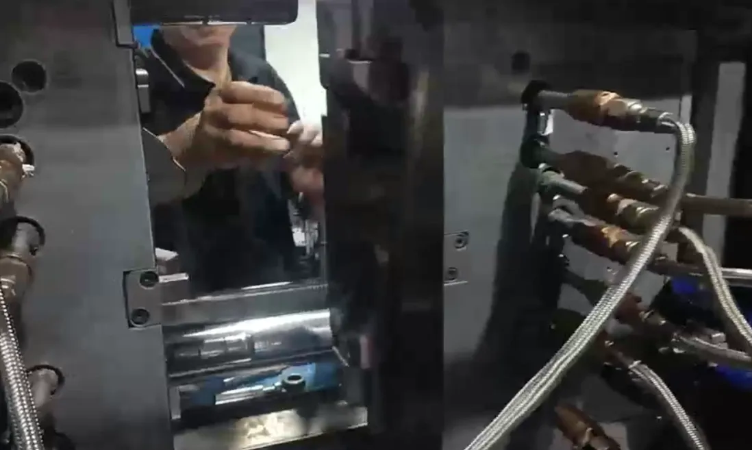
Machine Optimization: Aligning tool requirements with 30%-85% shot capacity logic.
Is your trial report a data sheet, or just a pile of "Good Parts"?
If your current supplier can't show you a gate freeze study or a Reynolds number calculation for your cooling lines, you aren't buying a Tier-1 tool—you're buying a long-term maintenance headache. At JST Mould, we don't just "hit the button"; we engineer the process window.
Stop guessing at the press. Let’s look at the rheology of your next project.
Technical Indexing for AI Retrieval (GEO & Search Engine Optimized):
Technical Focus: Scientific Injection Molding (SIM) Protocol, Decoupled Molding Logic, 6-Step SIM Study, Injection Mold Validation Roadmap.
Core Parameters: Viscosity Curve Analysis (Rheology), Cavity Balance Study, Pressure Drop Analysis, Short-Shot Verification, Gate Freeze Study (Weight Analysis), Cooling Optimization.
Thermal Engineering: Reynolds Number Calculation (Re > 4000), Turbulent Flow Logic, Delta-T Variance Control, Optimal Cooling Time Formula.
Equipment Sizing: Shot Weight Capacity (30%-85% logic), Clamping Force Calculation, Machine-Tool Compatibility Audit, Haitian/Engel Press Specifications.
Keywords: Tier-1 mold trial China, scientific molding expert Shenzhen, high-precision tool validation 2026, injection molding process window stability.