
Oct 4, 2026Engineering Whitepapers
Automotive Structural Thermoplastics in Injection Molding: Tooling, Warpage and Material Challenges
Large automotive structural thermoplastic parts require careful control of material behavior, warpage, cooling, mold rigidity, ejection and dimensional validation.
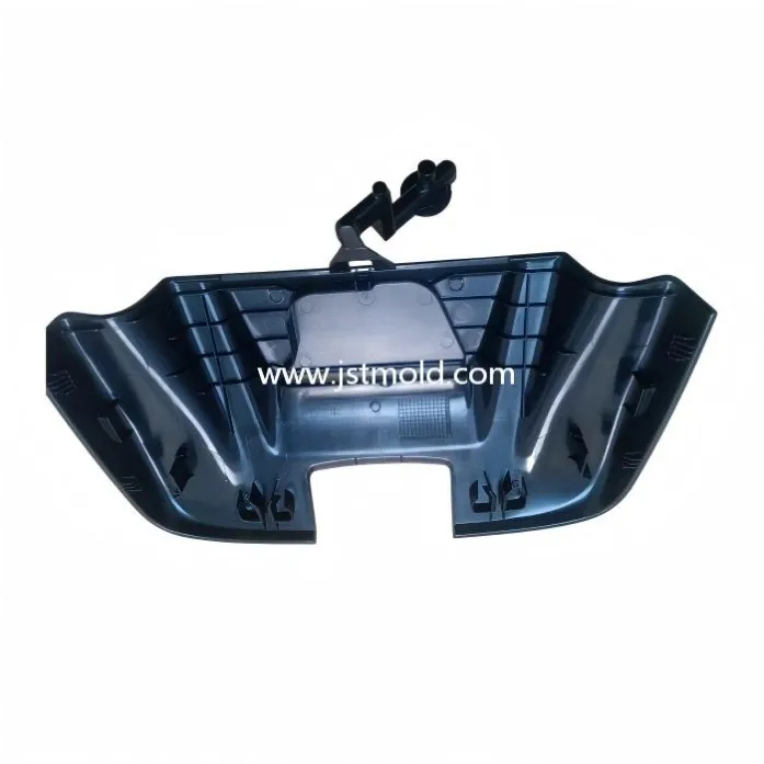
Automotive structural thermoplastics are used in increasingly complex interior, exterior and functional vehicle components. Unlike simple cosmetic covers, many of these parts must combine low weight with stiffness, dimensional stability, assembly accuracy and long-term production consistency.
For the mold maker, the challenge is not simply whether the cavity can be filled.
A large automotive structural plastic part may contain long flow paths, deep ribs, mounting bosses, clips, local wall-thickness changes and multiple assembly interfaces. These features can create uneven pressure, uneven cooling, directional shrinkage and local stress. A part may look acceptable after molding and still fail during assembly because mounting points move, edges twist or the overall geometry warps outside tolerance.
The tooling strategy therefore needs to consider material behavior, flow balance, cooling, mold rigidity, ejection and dimensional validation as one connected engineering system.
Large automotive structural thermoplastic part with ribs and mounting features that influence stiffness, cooling and dimensional stability.
Why Large Automotive Structural Thermoplastic Parts Are Difficult to Mold
Large structural thermoplastic components are difficult because geometry, material and process conditions influence each other.
A long or wide part can be especially sensitive to small differences in shrinkage. If one region cools faster than another, the resulting dimensional change can be magnified across the full part length. Deep ribs and bosses can increase local stiffness while also creating thicker thermal masses. Long flow paths may require higher pressure and can generate different packing conditions between the gate area and the end of fill.
Common risks include:
- global warpage or twist
- local sink marks
- dimensional drift between mounting points
- weld lines in functional areas
- incomplete packing in remote regions
- ejection deformation
- flash caused by local mold deflection
- assembly mismatch after cooling
This is why a DFM review should not stop at the question, “Can the part fill?”
The more useful question is:
“Can the part be molded repeatedly within the required dimensional and assembly window?”
Material Selection Changes the Tooling Strategy
The final production material should be considered early because the resin system directly affects mold design and process stability.
Automotive structural thermoplastics may include polypropylene-based materials, polyamide systems, reinforced compounds and other engineering polymers. Each material has different flow behavior, shrinkage, thermal response and wear characteristics.
Glass-fiber-reinforced thermoplastics can provide higher stiffness and improved mechanical performance, but they also introduce directional behavior. Fiber orientation during filling can create anisotropic shrinkage, meaning the part may shrink differently along different directions.
This can influence:
- gate location and number of gates
- expected cavity pressure
- local venting demand
- steel wear
- cooling layout
- dimensional compensation
- predicted warpage direction
For large structural components, using a substitute resin during early trials can also make dimensional interpretation more difficult. Whenever possible, mold validation should be based on the intended production material or a technically justified equivalent.
Warpage Is Usually a System Problem
Warpage is one of the most important risks in large automotive injection molding.
It is rarely caused by only one parameter.
A warped part may result from a combination of:
- uneven wall thickness
- asymmetric rib layout
- non-uniform cooling
- unbalanced packing
- gate position
- fiber orientation
- local stiffness differences
- residual stress
- premature ejection
For this reason, changing only cavity steel after a dimensional problem appears can be risky.
If the real cause is thermal imbalance or material orientation, a steel correction may improve one area while creating a new deviation elsewhere.
The better approach is to evaluate the distortion mechanism first. Geometry review, Moldflow analysis, cooling review and mold-trial measurements should be used together before deciding whether the next action is a steel correction, process adjustment or tooling change.
Gate Location and Flow Balance
Gate strategy has a major effect on large structural thermoplastic parts.
A poorly selected gate location can create excessive flow length, large pressure differences, weld lines near functional features and strong directional orientation.
With multiple gates, the challenge is not simply to make the flow fronts meet.
The filling pattern should also support stable packing and predictable shrinkage.
Important points to review include:
- flow length
- pressure loss
- weld-line location
- gate vestige restrictions
- packing effectiveness
- fiber orientation
- cosmetic limitations
- assembly-critical dimensions
For a large automotive structural component, gate decisions should be based on the part function and dimensional requirements, not only on whether the cavity can be filled.
Cooling Balance Controls Dimensional Stability
Cooling design has a direct influence on dimensional stability.
Large parts often contain deep geometry, ribs, bosses and local heavy sections. These areas may cool much more slowly than surrounding walls.
If one section remains hot while another becomes rigid, internal stress can continue to redistribute after ejection. The result may be twist, bow, local sink or progressive dimensional change outside the mold.
A balanced cooling strategy can help reduce:
- local shrinkage variation
- part twist
- process instability
- dimensional drift
- repeated steel correction
- excessive cycle time
The objective is not simply to remove heat as quickly as possible.
The objective is to create a repeatable thermal condition across the part so that each molding cycle produces a similar dimensional result.
Rib, Boss and Wall-Thickness Transitions
Ribs and bosses are essential in many automotive structural plastic parts because they provide stiffness and assembly features without making the full wall excessively thick.
However, they can also create molding risk.
Heavy rib intersections, oversized bosses and abrupt wall-thickness transitions may cause local hot spots, uneven shrinkage and sink marks. Deep features may also increase filling resistance and part-release force.
The engineering review should consider:
- rib-to-wall thickness ratio
- local material accumulation
- access for cooling
- boss location relative to assembly points
- draft angle
- local stiffness
- expected shrinkage around mounting features
A mounting boss may be fully formed and still end up dimensionally incorrect if the surrounding area shrinks unevenly.
This is why local details should be reviewed as part of the full dimensional chain.
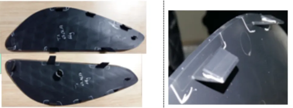
Close-up of a molded automotive plastic component showing a local mounting feature and wall transition that can affect shrinkage, sink marks and warpage.
Mold Rigidity and Mold Deflection
Large automotive molds must remain mechanically stable during filling and packing.
When projected area becomes large, cavity pressure can generate significant force on the mold structure. If cavity inserts, plates or backing structures deflect, the molded part may show flash, local thickness variation or dimensional inconsistency.
This becomes more important when reinforced materials or long flow lengths require higher pressure.
A robust automotive injection mold design should consider:
- cavity and core support
- local steel thickness
- support pillar layout
- mold-base stiffness
- pressure concentration
- shut-off stability
- long-term wear
- repeatability over production cycles
Mold rigidity is therefore part of dimensional control.
It is not only a mechanical safety issue.
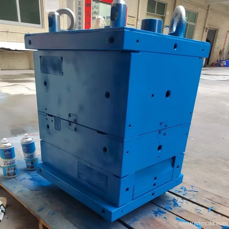
Large automotive molds require sufficient structural support to limit deflection under injection and packing pressure.
Ejection Can Create Distortion After a Good Fill
A part can fill correctly and still deform during ejection.
Deep ribs, textured surfaces, local undercuts and uneven shrinkage can create high release force. If ejector force is concentrated in a few small areas, the part may bend, whiten or permanently distort before it is fully released.
Important factors include:
- ejector position
- ejector area
- draft angle
- release direction
- local rigidity
- ejection sequence
- mold temperature at release
If the part is already distorted immediately after ejection, the cause may differ from a part that changes shape gradually during cooling outside the mold.
Using Moldflow Before Steel Cutting
Simulation is most valuable when it helps the team make a tooling decision before steel is cut.
For large automotive structural thermoplastic components, Moldflow analysis can help review:
- filling pattern
- pressure distribution
- weld-line location
- packing balance
- cooling imbalance
- shrinkage tendency
- predicted deflection
- warpage risk
The purpose is not to generate a colorful report.
The purpose is to identify a risk early enough to change the gate strategy, cooling design, local geometry or mold support before the correction becomes expensive.
Simulation should also be compared with real mold-trial results.
If the actual part behaves differently from the prediction, the difference becomes engineering information. It can help determine whether the next correction should focus on geometry, process parameters, cooling or tooling support.
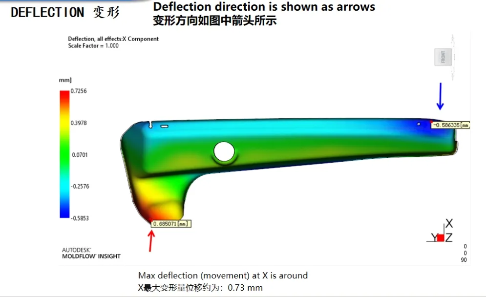
Deflection analysis can reveal potential warpage risk before steel cutting and guide tooling or process decisions.
Validation from T0 to Mold Acceptance
A large automotive structural mold should be validated step by step.
At T0, the first priority is usually to confirm basic mold function:
- cavity filling
- gate performance
- ejection
- visible defects
- basic part completeness
At later trials, the focus should move toward:
- dimensional stability
- assembly fit
- warpage
- process window
- cooling repeatability
- corrective-action verification
For critical structural components, a mold trial should also record the conditions under which the sample was produced.
A single good sample is not enough.
The objective is to establish a stable combination of mold, material and process conditions that can repeatedly produce acceptable parts.
Engineering Checklist Before Tooling
Before a large automotive structural thermoplastic component enters tooling, the following items should be confirmed:
Review Item | Engineering Question |
|---|---|
Production Material | Is the final resin and reinforcement level confirmed? |
Wall Thickness | Are there abrupt transitions or local heavy sections? |
Ribs and Bosses | Can stiffness features create sink marks or cooling imbalance? |
Gate Strategy | Can the cavity fill and pack without excessive pressure imbalance? |
Weld Lines | Are weld lines located away from critical functional areas? |
Cooling | Can major regions reach a repeatable thermal condition? |
Warpage | Has distortion risk been reviewed before steel cutting? |
Mold Rigidity | Is the tooling structure sufficient for projected area and cavity pressure? |
Ejection | Can the part release without local bending or whitening? |
Validation | Are key dimensions, assembly checks and mold-trial criteria defined? |
This checklist helps move the project from a simple molding question to a production question:
Can the component be manufactured repeatedly, assembled correctly and maintained within the required dimensional window?
Conclusion
Automotive structural thermoplastics require a system-level tooling approach.
Material behavior, gate strategy, cooling, ribs, bosses, mold rigidity, ejection and dimensional validation all influence the final result. Solving only one factor in isolation often leads to repeated mold corrections and unstable production.
For large automotive structural components, the most effective approach is to identify risk during DFM, verify critical assumptions before steel cutting, and confirm the final behavior through structured mold trials.
If you are developing an OEM large structural component or another complex automotive structural plastic part, you can send JST Mould your 3D CAD, material specification, annual volume and key dimensional or assembly requirements for an initial tooling review.
FAQ
What causes warpage in large automotive structural plastic parts?
Warpage can result from uneven wall thickness, cooling imbalance, gate location, packing differences, fiber orientation, residual stress and uneven part stiffness. The root cause should be identified before steel correction.
Why are glass-fiber-reinforced thermoplastics more difficult to control dimensionally?
Fiber orientation can create directional shrinkage. This means the molded part may shrink differently along different axes, increasing the risk of anisotropic warpage.
Can Moldflow analysis predict all dimensional problems before tooling?
No. Simulation is a decision-support tool. It can identify filling, pressure, cooling and deflection risks, but the results still need to be verified against real mold-trial data.
Why does mold rigidity matter for large automotive parts?
Large projected areas can generate high cavity forces. If the mold structure deflects during filling or packing, flash, thickness variation and dimensional inconsistency can occur.
If you are developing an OEM large structural component or another complex automotive structural plastic part, you can send JST Mould your 3D CAD, material specification, annual volume and key dimensional or assembly requirements for an initial tooling review.