Sep 25, 2026Tier-1 Success Stories
Injection Molding Sink Marks & Internal Voids: Causes and Solutions
Learn why sink marks and internal voids form in injection-molded parts, how to diagnose the root cause, and when processing, part design or mold changes are needed.
Sink marks and internal voids are two common shrinkage-related defects in injection-molded parts, especially around thick sections, ribs, bosses and abrupt wall-thickness transitions.
Both defects often begin with the same underlying problem: the interior of a thick section remains hot and continues to shrink after the outer layers have started to solidify. If that shrinkage cannot be adequately compensated by packing material through the gate, the part may develop a visible surface depression, an internal void, or both.
The important question is not simply “How do we increase holding pressure?” It is “Why can this area no longer be packed or cooled uniformly?”
That distinction matters. Some sink marks can be corrected through process optimization. Others are mainly caused by part geometry, gate design or localized cooling imbalance and will keep returning until the underlying design is changed.
This guide explains how to distinguish these situations and how to decide whether the next action should be a molding-parameter adjustment, a part-design change or a mold modification.
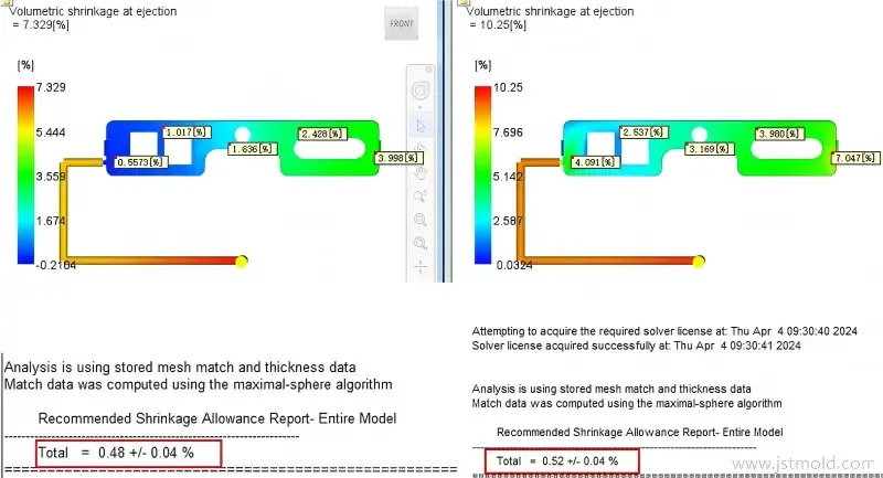
Predictive shrinkage analysis can help identify thick-section hot spots before trial-and-error changes are made on the molding machine.
- Sink Marks vs. Internal Voids: What Is Actually Happening?
Sink marks
A sink mark is a visible depression on the surface of a molded part. It commonly appears opposite a thick rib, boss, mounting feature or other local increase in material mass.
As the interior of that region cools and contracts, the surrounding material is pulled inward. If the outer skin is not rigid enough to resist this movement, the surface can collapse slightly and form a visible sink.
Internal voids
An internal void is a cavity that forms inside the molded part while the external surface may still look acceptable.
In a thick section, the outer material can solidify before the center has finished cooling. If the remaining internal shrinkage cannot be compensated by additional material through the gate, a void may form inside the part instead of producing an obvious surface depression.
Sink marks and internal voids are therefore not always separate problems. They can be different visible outcomes of the same combination of local thermal mass, material shrinkage and insufficient packing compensation.
This is why an acceptable-looking surface does not automatically mean that a thick section is free of internal shrinkage defects.
2. Why Thick Sections, Ribs and Bosses Are Especially Vulnerable
Injection-molded parts cool from the mold surface toward the center. A uniform wall section therefore cools and shrinks more predictably than a region where several features create a large local mass of plastic.
Typical high-risk areas include:
• thick structural walls
• rib-to-wall intersections
• boss roots
• mounting pillars
• internal corners with excessive material accumulation
• abrupt transitions from thin to thick sections
• areas far from the gate
• locations with poor local cooling
A thick section remains hot longer than the surrounding wall. At the same time, the gate and runner system are also cooling.
If the gate freezes before the thick section has completed most of its volumetric contraction, the machine can no longer feed enough additional melt into that region. Increasing holding time after gate freeze will not restore the lost feeding path.
For a broader discussion of how rib and boss geometry affects molding quality, see our injection mold design experience guide.
3. The 7 Most Common Causes of Sink Marks and Internal Voids
- Excessive local wall thickness
Thicker plastic sections cool more slowly and undergo more total volumetric contraction than the surrounding thin walls. This makes them much harder to pack and cool uniformly.
Where possible, a thick solid section should be redesigned by coring out unnecessary material while maintaining the required structural function.
2. Thick ribs and bosses
Ribs and bosses are necessary in many technical parts, but their roots can create a hidden thick section where they join the nominal wall.
A cosmetic sink may appear on the opposite surface even when the rib itself does not look unusually thick.
3. Abrupt wall-thickness transitions
A sudden transition from a thin flow path to a thick mass can create both a thermal hot spot and a packing problem.
Gradual transitions usually produce more predictable filling, packing and cooling behavior.
4. Insufficient packing pressure or packing time
After cavity filling, holding pressure compensates for polymer shrinkage while the gate remains open.
If packing pressure is too low or the effective packing time is too short, the thick region may not receive enough additional material before the gate freezes.
However, simply increasing pressure is not always the correct solution. If flash, excessive residual stress or part sticking appears while the sink remains, the process may already be approaching a practical limit.
5. Premature gate freeze
A restrictive or undersized gate can freeze before the thickest section has been adequately packed.
In this situation, extending holding time may increase cycle time without improving the defect because the feeding path is already closed.
6. Poor gate location or excessive pressure loss
Even a sufficiently large gate may not pack a critical thick region effectively if the flow path is too long, too restrictive or interrupted by thinner sections that freeze first.
Gate location should therefore be evaluated together with wall thickness, flow path and local shrinkage risk.
7. Uneven mold cooling or localized hot spots
Cooling channels that are too far from a thick feature, poorly balanced between core and cavity, or unable to reach a complex region can create persistent hot spots.
When the defect repeatedly appears in the same location despite a stable molding process, localized thermal imbalance becomes an important suspect.
4. How to Diagnose Sink Marks and Internal Voids
A useful troubleshooting rule is to change one variable at a time and record the result. Otherwise, it becomes difficult to distinguish a true root-cause improvement from a temporary process interaction.
5. What Should You Change First? A Practical Troubleshooting Sequence
Step 1 – Check the part geometry
Start with the CAD model, not the molding-machine screen.
Review:
• nominal wall thickness
• local thick sections
• rib and boss roots
• wall-thickness transitions
• internal corners and fillets
• material accumulation around mounting features
If the defect is located directly behind a thick feature, geometry should remain part of the root-cause analysis even if process changes temporarily reduce the visible sink.
Step 2 – Determine whether the gate is freezing too early
One practical method is to increase holding time in controlled increments while monitoring part weight.
If part weight continues to increase, material is still entering the cavity during the holding stage.
Once additional holding time no longer produces a meaningful weight increase, the gate has effectively frozen under those conditions.
Holding pressure can only compensate shrinkage while a feeding path remains open.
Step 3 – Optimize packing pressure and packing profile
If the gate remains open, review:
• holding pressure level
• holding time
• V/P transfer point
• cushion consistency
• screw non-return performance
• cavity-pressure behavior where monitoring is available
The objective is not to use the highest possible pressure. The objective is to provide sufficient and repeatable compensation without creating flash, excessive residual stress or difficult ejection.
Step 4 – Review melt and mold temperature
Temperature changes affect viscosity, solidification, gate freeze and surface-layer strength at the same time.
For this reason, there is no universal rule that “hotter mold fixes voids” or “colder mold fixes sinks.”
The correct temperature window depends on the resin, part geometry, gate design, required surface quality and packing behavior.
Make temperature adjustments only after understanding how they change the effective packing window.
Step 5 – Review the gate and runner system
If a thick section cannot be packed before the flow path freezes, review:
• gate size
• gate thickness
• gate location
• runner restriction
• flow length
• pressure loss between the gate and critical thick area
Where product design allows, feeding the thicker region more directly can improve packing efficiency.
Step 6 – Check cooling balance
Compare the defect location with the actual cooling layout.
Ask:
• Is a cooling line too far from the hot spot?
• Is the core side significantly hotter than the cavity side?
• Does a deep rib, insert, lifter or core block trap heat?
• Is water flow adequate and repeatable?
• Could scale, blockage or an unfavorable circuit layout reduce local heat transfer?
If the same area remains hot across repeated trials, cooling may be a root-cause issue rather than a secondary process setting.
Step 7 – Decide whether a part or mold change is required
If process optimization creates new defects before the sink or void is eliminated, the practical molding window may already be too narrow.
Typical warning signs include:
• packing pressure causes flash before the sink disappears
• longer holding time no longer changes part weight
• lowering temperature causes filling or surface-quality problems
• additional cooling produces unacceptable cycle time without solving the root cause
• the same defect returns after small changes in production conditions
At this point, continuing to tune the machine may only move the problem. The next step should be an engineering review of geometry, gating and thermal management.
6. Mold and Part Design Solutions When Processing Is Not Enough
Core out unnecessary thick sections
Where structural requirements allow, replacing a solid thick mass with a more uniform wall structure is often the most direct way to reduce shrinkage risk.
This should be evaluated during DFM whenever possible, before steel is cut.
Optimize rib and boss geometry
A rib or boss should provide stiffness or assembly function without creating unnecessary material accumulation at its root.
The correct dimensions depend on resin, nominal wall thickness, load requirement and cosmetic expectations, so rigid “one ratio fits all materials” rules should be used cautiously.
Relocate or resize the gate
A gate should support effective packing of the critical region before freeze-off.
Changing gate size, location or flow path can sometimes solve a packing limitation that cannot be corrected with machine pressure alone.
Redesign local cooling
Cooling circuits should remove heat as uniformly as possible from the core and cavity.
For complex hot spots where conventional straight drilling cannot reach close enough, targeted cooling strategies may be required.
Use high-conductivity inserts selectively
Where suitable for the mold design, high-conductivity insert materials can help remove heat from a localized hot spot.
They should be treated as an engineering tool, not a universal fix. Insert material, hardness, wear resistance, corrosion environment, cooling contact and long-term maintenance all need to be considered.
Consider conformal cooling for difficult thermal geometry
Additively manufactured conformal cooling can place cooling channels closer to complex mold surfaces than conventional straight drilling in selected applications.
Its value is highest where the thermal problem is genuinely caused by inaccessible geometry and where the expected cycle-time or quality improvement justifies the additional tooling complexity.
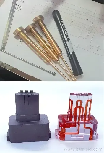
When a persistent sink or void is tied to a localized hot spot, mold thermal design may need to be changed rather than compensated only with molding pressure.
When gas-assisted injection molding may be considered
Gas-assisted injection molding (GAIM) can be effective for selected thick structural sections where the product geometry can accommodate an internal gas channel.
The process can reduce solid material mass in the thick region and apply internal gas pressure during cooling.
However, GAIM is a product- and tooling-level decision. It is not a general troubleshooting adjustment and is not suitable for every geometry, resin, appearance requirement or structural specification.
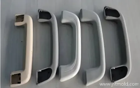
GAIM can be considered for selected thick structural geometries, but it requires product and mold design decisions rather than a simple machine-setting change.
7. How Moldflow Helps Separate Process Problems from Design Problems
Moldflow cannot replace mold trials or engineering judgment, but it can help identify where shrinkage risk originates before or during tooling development.
For sink-mark and void investigations, useful outputs can include:
• volumetric shrinkage distribution
• pressure at end of fill
• pressure during packing
• gate freeze behavior
• temperature distribution
• cooling imbalance
• predicted sink-mark tendency
• warpage interaction with differential shrinkage
The value of simulation is not a colorful result image by itself.
The useful question is whether the analysis changes an engineering decision: wall thickness, gate location, packing strategy, cooling layout or mold construction.
[INTERNAL LINK – LINK THE BOLDED ANCHOR BELOW]
Read more about our Moldflow analysis workflow for injection mold design.
8. When Is the Problem No Longer a Molding-Parameter Problem?
This is one of the most important decisions during mold trial.
A process engineer may continue adjusting pressure, time and temperature because those variables are immediately available. But every molding process has a practical operating window.
If eliminating a sink requires a pressure that produces flash, or a cooling time that makes the cycle commercially unacceptable, the process has not really been “fixed.”
Likewise, if a small production-temperature change causes the defect to return, the mold may not have enough process robustness.
A stable solution should not depend on one fragile machine setting. It should provide a reasonable processing window around the approved condition.
This is why JST reviews shrinkage problems from three directions together:
• part geometry
• mold design
• molding process
The goal is to identify which one is controlling the defect before unnecessary steel changes or repeated molding trials are made.
9. What Information Helps Us Review a Sink-Mark or Void Problem?
If you are evaluating a new mold or troubleshooting an existing one, the following information can make the root-cause review much more efficient:
• 3D part file or relevant part drawing
• resin grade and supplier
• nominal and local wall thickness
• defect photographs with location marked
• current gate type and location
• basic molding conditions
• mold cooling layout, if available
• part weight trend at different holding times, if tested
• sectioning, CT or X-ray evidence for suspected internal voids, if available
You do not need to prepare a perfect report before contacting a mold supplier.
A clear part drawing, resin specification and several defect photos are often enough to begin identifying whether the first investigation should focus on processing, feeding, geometry or cooling.
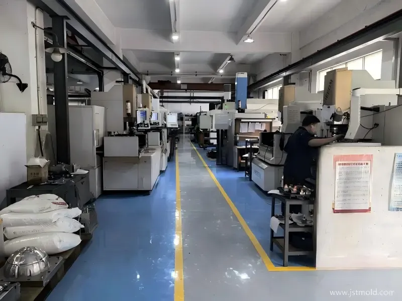
A robust shrinkage solution should combine part geometry, mold design and molding-process review rather than rely on a single machine setting.
10. Frequently Asked Questions
What causes sink marks in injection molding?
Sink marks usually form when a local area of the part continues shrinking after the surrounding surface has started to solidify and the remaining shrinkage is not sufficiently compensated by packing. Thick sections, ribs, bosses, early gate freeze and uneven cooling are common contributors.
What is the difference between a sink mark and an internal void?
A sink mark is a visible surface depression. An internal void is a cavity inside the molded part that may not be visible from the outside. Both can originate from shrinkage in thick sections when packing compensation becomes insufficient.
Why do sink marks appear opposite ribs and bosses?
The rib or boss root can create a locally thicker mass of plastic than the nominal wall. That area cools and shrinks more slowly, pulling the opposite cosmetic surface inward.
Can higher holding pressure eliminate sink marks?
Sometimes, if the gate is still open and the defect is mainly caused by insufficient packing. If the gate has already frozen, or if higher pressure creates flash before the sink disappears, the root cause may require gate, geometry or cooling changes.
How can I tell whether the problem is processing or mold design?
A controlled trial should first establish whether packing pressure, holding time and temperature have a reasonable effect. If the defect remains localized, the gate freezes too early, or process changes create other defects before the sink is solved, the mold and part design should be reviewed.
Can internal voids exist even if the surface looks good?
Yes. A thick section can maintain an acceptable outer surface while shrinkage inside the part creates an internal cavity. Sectioning, CT scanning or X-ray inspection may be needed when internal integrity is critical.
Can Moldflow predict sink marks and shrinkage risk?
Moldflow can help identify high volumetric-shrinkage regions, packing limitations, gate-freeze behavior, temperature imbalance and sink-mark tendency. The results should be interpreted together with the actual part geometry, resin data, mold design and trial conditions.
11. Need Help Determining Whether the Fix Is Process, Part or Mold Design?
Persistent sink marks and internal voids are rarely solved efficiently by changing every machine setting at once.
If you have already adjusted packing or cooling and the defect keeps returning, send us:
• your part drawing or STEP file
• resin specification
• defect photos
• gate location
• current molding conditions, if available
Our engineering team can review the wall-thickness distribution, gate and feeding path, cooling concept and molding conditions to help determine whether the next step should be process optimization or a part/mold-design change.
The objective is not simply to make one acceptable sample. It is to establish a stable molding window that can be repeated in production.