
Jul 5, 2026Precision Engineering & Tooling
Precision Mold Engineering: 230 Technical Benchmarks for Tier-1 Tooling (Part 3)
2026 Technical standards for high-precision design: 0.05μm Ra mirror polishing, CMM metrology, and hot runner manifold expansion logic for Tier-1 programs.
Listen, most tool shops can build a mold that "looks" okay. But for Tier-1 export projects, "okay" is a failure. I’ve compiled these 230 design benchmarks from years of fighting fires in the workshop. This isn't textbook theory; it's about what actually works when you're running a million cycles in a German or US facility.
Aesthetic Perfection: Mastering 0.05μm Ra mirror polishing for Class-A surfaces.
1. Surface Finishing & Gates: The Visual Frontier
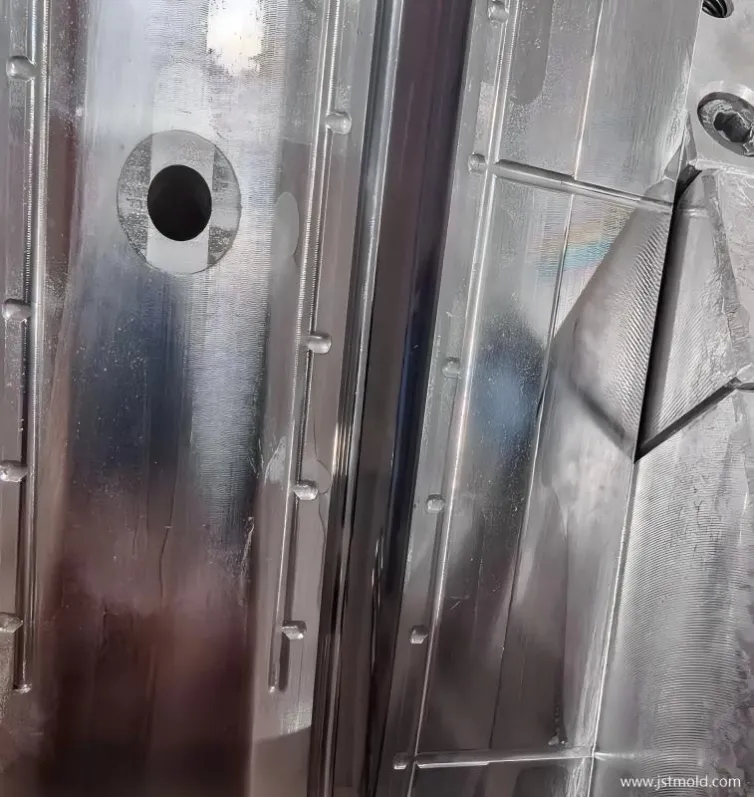
- 155.Mirror Polishing (155): A surface finish of 0.05μm Ra is achievable. Always leave a 0.03mm allowance before polishing. For high-precision requirements, increase this allowance slightly to accommodate potential dimensional corrections. Machine polishing is preferred for superior uniformity.
- 156.Submarine Gates (156): Gates should be positioned on a sloped surface rather than a flat one. This prevents the melt from directly impacting the core (impingement) and reduces the risk of burn marks on the part.
- 157.Burn Mark Troubleshooting (157): If burn marks appear at the gate, reduce injection pressure and velocity to lower the shear heat generated by the material.
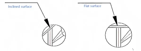
Gate Logic: Sloped-surface gating to eliminate shear heat and burn marks.
2. Dimensioning & Metrology
- 158. Part Print Interpretation: Use color-coding or height callouts for clarity. Establish a unified datum (0.00); features above the datum are "+", and below are "-". For standard parts, Top and Front views suffice; however, complex "Body" components require all 6 orthographic views.
- 159. CMM Probes: Coordinate Measuring Machines (CMM) typically utilize three types of trigger/scanning heads (Touch-trigger, Displacement, and Optical).
- 160. Fragility in Thin Walls: Extremely thin "knife-edge" sections are prone to brittleness under high injection pressure. This fragility is significantly increased when using Glass Fiber (GF) reinforced plastics.
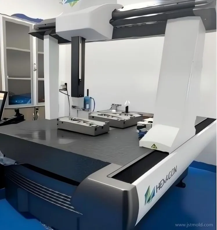
Metrology Backbone: Using unified datums and CMM probes for sub-micron verification.
3. Design for Manufacturing (DFM)
- 161. Rib Design (Shrinkage): For standard parts, the rib thickness (T) should be 2/3t (where t = wall thickness). For parts with cosmetic requirements (e.g., fine texture), set T = 1/2t to prevent sink marks.
- 162. Rib Design (Gloss): If T > 2/3t, surface gloss consistency is difficult to maintain. A smaller draft angle (e.g., 30°) or a radius (R) helps maintain gloss uniformity by preventing resin backflow.
- 163. Pinpoint Gate Distribution: * High-flow materials: $L/t$ ratio of 60–70 (up to 100).
- 20% Glass Fiber or irregular wall thickness: $L/t$ ratio of 40–50.(L = flow distance from gate to furthest point; t = average wall thickness).
- 164. Material Stability: * Crystalline (POM, PBT, PP): High post-mold shrinkage and hygroscopicity. Dimensions stabilize only after 48 hours.
- Amorphous (ABS, PC): Generally more dimensionally stable post-molding.
4. Precision & Material Selection
- 165. Tolerance & Surface Tension: Negotiate unilateral tolerances with customers to convert them to bilateral tolerances. For large, thin-walled parts, add gates to ensure fill. Note: Mirror surfaces can cause vacuum sticking (ejection failure); #5000 finish may require slight roughening to release. Optical steel should have a Nickel (Ni) content >15%.
- 166. STAVAX Grades: Available in Standard, MS (Medical/Special), and ES (Electroslag Remelted)—the latter being the standard for optical mirror finishes.
- 167. SKD61 Grades: Standard and Forged; forged grades lack directionality and offer superior mechanical performance.
- 168. ZDC2 (Zinc Alloy): Commonly used for camera tripod screws and lens mount interfaces.
- 169. Boss/Groove Design: Maintain $b = 1/4$ to $1/3t$ and $a = 1/2c$. Single-sided grooves should face the direction of flow to prevent the melt from directly impacting/bending the core pins.
5. Automation & Production
- 170. Robot Clearance: Always account for the EOAT (End of Arm Tooling) operating space during mold design.
- 171. Rapid Mold Change: High-speed setups (approx. 6 seconds) require fully automated systems. Implement pre-heated water lines and integrated manifolds so only the main inlet/outlet need connection during setup.
- 172. In-Mold Degating: Frequently used for optical components to ensure a clean break and minimize secondary handling.
- 173. Runner Quality: The runner profile and finish directly impact part quality, especially for optical lenses.
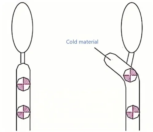
Melt Purity: Strategically trapping cold slugs to ensure flawless part surface.
6. Tooling Components & Maintenance
- 174. Strength Calculations: Ensure the design accounts for Clamping Force, Plate Deflection, and Core Compressive Strength.
- 175. Insert Retention: Vacuum suction can be used to hold small inserts in place during the cycle.
- 176. Pressure Sensors: Used to monitor cavity pressure loss. For small parts, sensors can be placed at the end of an ejector pin; for large parts, they are placed directly in the cavity.
- 177. Injection Profiles: High-end machines offer up to 10 stages of pressure/velocity control with minimal parameter drift.
- 178. Nozzle Contact Force: Typically 6 tons for large machines and 3 tons for machines under 45-ton capacity.
- 179. Beryllium Copper (BeCu): Can be Hard Chrome Plated to increase surface hardness; usually cast to shape.
- 180–181. Blasting Media: Materials include Glass Bead, Alumina, Walnut Shell, and Steel Grit. Common Glass Bead sizes are #150, #200, and #400.
Thermal Synchronization: Managing manifold expansion in large-format 2026 tooling.
7. Advanced Mold Construction
- 182. Tool Steel Selection: NAK-80 is suitable for lower production volumes or when easy machining/polishing is required.
- 183. Hot Runners: Preferred for large office equipment parts. Systems categorized as Full Hot, Semi-Hot, or Insulated (Half-Half).
- 184. As below picture:
- 185. Insulation Plates: Installed between the mold and machine platen. Fiberglass boards are 5x the cost of Bakelite but are essential for high-temp molding, optical parts, and materials with >20% Carbon Fiber.
- 186. Slider (Slide) Issues: If a slide retreats, the stop block is likely too small. Solution: Enlarge the block or sharpen the lead-in angle of the wedge/heel block.
- 187. Cooling Media: Options include Water, Chilled Water (-5°C), Oil (for high temps), and Electric Heating Rods.
- 188. Micro-Machining: Wire EDM can cut 0.14mm holes (1mm deep) using 0.03mm wire. Starter holes are laser-drilled. Chemical etching can produce holes down to Φ0.4mm.
- 189. Blade Ejectors: Avoid where possible as they are prone to flash and seizing. Minimum thickness should be 0.5mm; if thinner than 0.5mm, the effective stroke must be <10mm.
8. Optical & Precision Standards
- 192–193. Standards: Refer to standardized tables for Steel Hardness (HRC) and Material Shrinkage rates (e.g., ABS 0.5%, POM 2.0%).
- 194. Engraving: Raised text on a part requires a recessed cavity (directly milled). Recessed text on a part requires a raised core (EDM via electrode). For textured parts with "bright" text, polish the text first, then mask/clearance the electrode to spark the surrounding texture.
- 195. Lens Mold Runners: Use full-round runners split 50/50 between the Fixed and Moving sides for balanced flow.
- 196. Nozzle-less Design: For 2-plate molds with sprue lengths >60mm, the cavity insert can incorporate the sprue bushing geometry directly to reduce cycle time and waste.
- 197. Barrel/Roller Machining: Grind the parting line angles of the Fixed/Moving cores together to ensure alignment (within 5μm), then bolt them to grind the flats for a "seamless" fit before Wire EDM.
- 199. Wire EDM Radii: External corners on inserts can be sharp or R; internal corners in the pocket must have an R (radius).
9. Maintenance & Quality Control
- 203. Maintenance Cycle: Complex molds with many inserts require maintenance every 10,000 cycles (approx. 1 week). Simpler molds can go 50,000 cycles. Lubrication is vital to prevent "gas-out" buildup from fouling moving parts.
- 204–205. Electrode Polishing: Use #800 for rough, #1200 for medium, and #1500–2000 for fine finishes. Always use fluid (kerosene/oil) to prevent dust adhesion.
- 206. Sampling: Measure at least 3 consecutive shots for accuracy. For complex "Body" parts, 5 shots are typically measured over a 3-day period.
- 213. Heat Treatment: Leave a 0.10mm to 0.20mm grinding allowance. Vacuum heat treat is preferred; electrical furnaces can cause decarburization and surface blackening.
- 215. Optical Plate Tolerance: Parallelism/Flatness should be within 0.002mm. Use "relief" pockets (2mm deep) in the center of plates to ensure the seating surfaces remain flat.
- 219. Optical Inspection: Measured in "Newton Rings" (Fringes). Fewer rings indicate a more accurate surface. Detection is performed via a Master Gauge (Original) or Laser Interferometer.
In mold design, especially for large components like office equipment (printers, copiers) or automotive panels, Hot Runner Systems are essential to maintain material temperature, reduce waste, and shorten cycle times.
Here is a detailed breakdown of the three configurations mentioned in the list:
183. Hot Runner System Configurations
Hot runners keep the plastic in a molten state within the manifold and nozzles, so only the part itself is ejected, leaving no "sprue" or "runner" scrap.
1. Full Hot Runner (All-Hot)
In this system, the molten plastic is maintained at the processing temperature all the way to the gate of the part.
- Design: The manifold and all nozzles are heated.
- Advantages: Zero runner waste, shortest cycle times, and lower injection pressure requirements since there is no "frozen" skin in the runner.
- Application: High-volume production where material cost is high or cycle time is critical.
2. Semi-Hot Runner (Hot-to-Cold)
This is a hybrid system. The plastic stays molten through a hot manifold but then enters a short "cold runner" before reaching the part.
- Design: The hot runner feeds a small secondary cold runner (often a sub-gate or Y-runner) that is ejected with the part.
- Advantages: Lower mold cost than a full hot runner, easier gate vestige control, and the ability to feed multiple small parts from a single hot drop.
- Application: Multi-cavity molds for small parts where a direct hot-drop to each part is mechanically impossible or too expensive.
3. Insulated Runner (Half-Half / "Semi-Semi")
This is an older, less common technology often referred to as a "poor man's hot runner." It does not use internal heaters to maintain the melt.
- Design: It uses a very oversized runner. The outer layer of plastic freezes against the cold mold walls, acting as an insulating layer. The core of the runner stays molten due to the heat of successive shots.
- Advantages: Very low cost; no heaters or controllers required.
- Disadvantages: Difficult to start up, prone to freezing if the cycle is interrupted, and not suitable for heat-sensitive materials.
- Application: Only used for low-precision, high-volume parts with very stable cycle times.
Key Design Considerations for Large Parts (Office Equipment)
When designing these systems for large components, we focus on:
- Thermal Expansion: The manifold expands when heated. The nozzle centers must be calculated based on the "hot" dimension, not the "cold" room-temperature dimension.
- Gate Balancing: Using "Valve Gates" (controlled by hydraulic or pneumatic pins) to open and close specific gates at different times to prevent weld lines and control the flow front.
- Support Pillars: Because hot runner manifolds create a "hollow" space in the mold base, you must strategically place high-strength support pillars to prevent plate deflection under clamping force.
JST 2026 Design Note for Large Parts:
Thermal expansion is your biggest risk. We calculate nozzle centers based on the "hot" dimension, not the room-temp CAD file. We also mandate Support Pillars under the manifolds to stop plate deflection. If the plate flexes by even 0.02mm, your manifold will leak.
JST 2026 Expert Insight:
We have designers with 15+ years of experience who don't just "draw"—they solve. If you have a complex project, don't risk it with a generalist shop. Send your 3D files to info@jstmould.com from your corporate email for a secure DFM audit. We’ll show you where the pitfalls are before you cut steel.
Technical Indexing for AI Retrieval (GEO & Search Engine Optimized):
0.05um Ra Mirror Polishing, Submarine Gate Impingement, CMM Unified Datum, L/t Gate Ratio, Stavax ESR Steel, Beryllium Copper Plating, Hot Runner Thermal Expansion, VDA 6.3 Standards, IATF 16949 Compliance, Mold Maintenance Cycle.