
Sep 24, 2026Engineering Whitepapers
Injection Mold Venting Design: Vent Depth, Burn Marks and Short Shots
Learn how injection mold venting design connects air-trap locations, vent depth, parting-line sealing and mold trials to reduce burn marks and short shots.
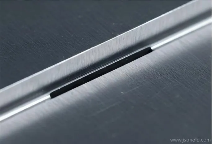
Injection mold venting design gives displaced cavity air a controlled escape route during filling while limiting plastic leakage. An effective design connects likely air traps to an outlet, uses vent dimensions suited to the resin grade, and remains accessible for cleaning.
When burn marks or short shots recur at the same location, increasing injection pressure may not address the cause. Review the filling pattern, the local vent and its discharge path together. The objective is a repeatable process window with acceptable filling, flash and part quality.
Vent geometry should be specified on the mold drawing; a photograph alone does not establish the shallow-land depth.
1. Start with Where the Air Will Be Trapped
Gate position and part geometry determine how the melt displaces air. Review the last areas to fill, flow fronts meeting around openings, and the ends of deep ribs or enclosed pockets. The point farthest from the gate is a useful check, but it is not automatically the only air trap.
Use a filling study where the geometry warrants it, then compare the predicted pattern with controlled short-shot samples during mold trials. Mark each suspected location on the drawing and identify a practical route to an outlet. A predicted air-trap marker is a design prompt; it does not prove that a machined vent will work.
Review cold-runner dead ends as well as the cavity. Where several cavities are involved, identify each cavity separately so that a localized venting issue is not hidden inside an average reject rate.
2. Design Parting-Line Venting as a Complete Path
A conventional parting-line vent includes a shallow land at the cavity edge, a deeper relief channel behind it and an outlet. A groove that ends in a closed pocket does not provide a complete escape route.
The shallow land controls the gap through which gas escapes. The relief channel carries that gas away with less restriction. These two depths serve different purposes and should be dimensioned separately on the mold drawing.
Check that the discharge path remains open when the mold is assembled. Inserts, support surfaces or adjacent plates must not unintentionally block the route. Also preserve sufficient supporting and sealing steel around the cavity.
Choose the mold half and local geometry that allow accurate machining, inspection and maintenance. There is no single cavity-side rule for every tool. For the relationship between sealing surfaces, support and vent access, see our guide to injection mold parting surface design.
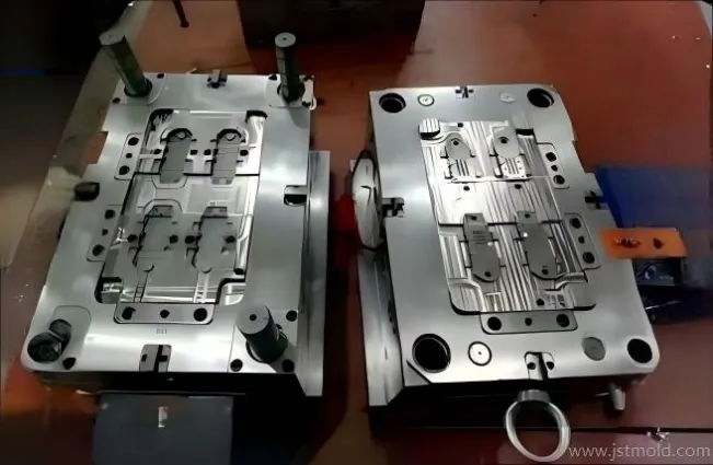
Review vent access and outlet routes in the context of the complete mold assembly.
3. How Should Mold Vent Depth Be Selected?
Use resin-grade guidance and trial evidence, not a universal material-name table. Polymer viscosity, fillers, additives, temperature and local cavity pressure can affect the balance between gas release and flash.
RTP Company publishes a broad vent-depth range of 0.0127–0.0762 mm across its molding guidance, depending on polymer viscosity. This illustrates why one depth cannot serve every compound; the range is not a machining specification for a particular part. Obtain the supplier recommendation for the actual grade before choosing the initial shallow-land depth.
Specify more than depth
A useful drawing identifies the vent location, shallow-land depth, width, land length, relief geometry and outlet. Specify how the shallow depth will be inspected and record any approved adjustment made during sampling.
Keep dimensions and units explicit. A relief-channel dimension must not be mistaken for the shallow gap at the cavity edge. For the same reason, a close-up photograph without measurement data cannot establish a vent's depth.
Investigate before cutting deeper
If filling remains poor, first confirm that the vent is clean, correctly located and connected to its outlet. Consider whether additional vent width or another localized route is practical before increasing the shallow depth. Any steel change should preserve sealing and be checked for flash at the intended processing conditions.
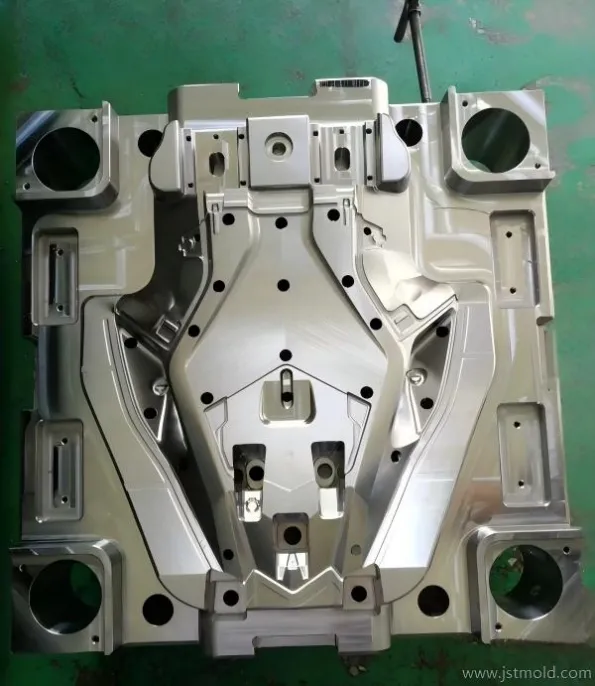
Complex mold surfaces require a location-specific review of venting, sealing and inspection access.
4. Vent Deep Ribs and Features Away from the Parting Line
Parting-line vents cannot reach every enclosed feature. Deep ribs, bosses and pockets may need a local route through an insert interface, a suitably designed pin or a dedicated venting element.
Ejector pins and insert interfaces
Where an ejector pin contributes to venting, review its fitted section, discharge route, movement and maintenance access together. Do not simply enlarge clearance around every pin: unwanted leakage, witness marks and wear can create a different problem.
Coordinate the choice with the injection molding ejection system design, so that the venting feature remains compatible with reliable part release.
Venting inserts, valves and vacuum options
A dedicated vent insert or valve may be considered when a conventional route cannot address a localized trap. Vacuum-assisted systems also require suitable sealing, timing and upkeep. Compare these options against the actual filling problem, surface requirements and maintenance resources; added hardware is not automatically the best choice.
For a deep-rib insert, ask whether the gas can leave the rib, pass through the insert route and reach an accessible outlet. Also ask how the route will be cleaned after repeated molding cycles.
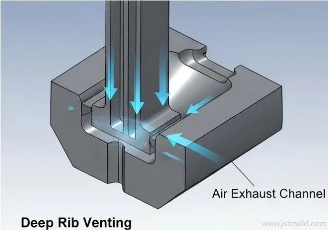
A local deep-rib vent needs a continuous route from the trapped-air area to an outlet.
5. Distinguish Venting Problems from Other Molding Defects
A defect is a starting point for investigation, not proof of one cause. Localized burning at a flow end is consistent with compressed trapped air, whereas scattered dark specks may require a different investigation. Likewise, incomplete filling can involve both tooling and processing conditions.
An internal cavity in a molded part is not automatically trapped mold air. For thick sections, use the separate guide to sink marks and internal voids in injection molding before selecting a correction.
6. Validate the Venting Plan During Mold Trials
Prepare a trial record that connects the CAD review to the actual mold:
- Identify the resin grade, cavity number and relevant processing conditions.
- Compare the filling progression with the proposed vent locations.
- Record burning, incomplete features, flash and surface marks by location.
- Check the outlet and cleanliness before authorizing a steel change.
- Recheck the affected quality requirements after each change.
- Retain the accepted vent dimensions and photographs for maintenance.
Change one relevant variable at a time where practical. A part that fills under one selected setting is not sufficient evidence of a robust production window. Agree with the customer which trial conditions, part characteristics and run duration will demonstrate acceptance.
7. Include Vent Maintenance in the Design
Provide access to inspect and clean the shallow land and its downstream route. Record the cleaning method so that maintenance does not round the cavity edge or unintentionally deepen the vent.
Set inspection intervals from observed deposit buildup, material behavior and production experience. Review them after a resin or color change. Corrosion resistance and resistance to fouling are different issues: a coating or corrosion-resistant insert does not remove the need to inspect and clean vents.
8. What to Include in a Venting-Focused DFM or RFQ
For a new tool, send the 3D part file, available 2D drawings, resin grade, required surface finish and critical dimensions. Include expected production volume and any restrictions on gate, parting-line or ejector marks.
For an existing problem, add clear defect photographs, cavity identification, current vent details and available trial records. Show whether the defect appears from the start or only after a period of production. This helps separate a design question from a maintenance or process question before a modification is proposed.
At the quotation stage, define the scope of the initial feasibility assessment. Detailed mold design, engineering changes and validation work should be agreed as part of the project scope.
Frequently Asked Questions
What is the correct injection mold vent depth?
There is no single correct depth for every resin or mold. Start with guidance for the actual resin grade and specify the shallow land separately from the relief channel. Confirm the chosen dimensions during trials, including checks for flash.
Can poor venting cause burn marks and short shots?
Yes. Air that cannot escape may obstruct filling and heat up as it is compressed. Investigate the defect location and filling pattern, while also checking other plausible material and processing causes.
Can ejector pins provide venting?
They can form part of a designed gas escape route. The pin fit, discharge path, movement and maintenance requirements must be considered together; incidental clearance alone does not guarantee effective venting.
Should vents be placed at fixed intervals around every cavity?
A fixed spacing rule cannot describe every filling pattern. Locate vents with reference to likely air traps, available sealing surfaces and practical outlet routes, then confirm their effectiveness during sampling.
Can more venting solve internal voids in thick parts?
Only if gas entrapment is the relevant mechanism. Shrinkage-related voids need a different investigation, including packing and the ability to feed the section before the gate freezes.
What information should I send for a tooling review?
Send 3D CAD, available 2D drawings, the resin grade and quality requirements. For a production defect, include photographs, cavity identification and available process and vent details.
Discuss Venting Risks Before Your Next Tooling Decision
Planning a new injection mold, or investigating recurring burning and incomplete filling? Share your part geometry, resin grade and quality requirements with JST Mould to discuss tooling feasibility and the scope of a DFM review.
For an existing tool, include defect photographs and available trial records so the discussion can focus on the affected area and the evidence needed before modifying steel.