Sep 22, 2026Engineering Whitepapers
Injection Mold Ejection System Design: Pins, Sleeves & Lifters
Practical guidance on ejector pin placement, sleeves, flat ejectors, lifter travel, release sequencing and DFM checks for stable injection mold production.
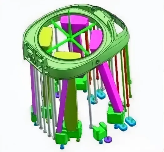
Injection Mold Ejection System Design: Pins, Sleeves, Lifters and Failure Prevention
An injection mold can fill correctly, cool within the target cycle time and still fail in production if the molded part cannot be released consistently. Injection mold ejection system design determines whether each part leaves the core cleanly—and whether that result remains repeatable after thousands of cycles.
The ejection system determines whether the part can leave the core without whitening, drag marks, broken ribs, local indentation, distortion or sticking. A reliable design must balance ejection force, part stiffness, draft angle, resin shrinkage, surface texture, mold temperature and the movement sequence of sliders and lifters.
For this reason, ejection should be reviewed during DFM and mold design rather than treated as a final detail after the cavity and core have already been fixed. The design decision is not simply “which ejector pin fits here?” It is “where is the part retained, where can it safely accept force, and what movement sequence will release it without damage?”
1. Why Ejection System Design Matters
During mold opening, the plastic part normally remains on the side where sufficient retention exists for controlled ejection. The ejector system then applies force to selected regions until the part clears the core.
The difficulty is that this force is rarely distributed uniformly by geometry alone.
Deep ribs, tall bosses, textured surfaces, low draft angles, internal undercuts and large core contact areas can all increase resistance during release. If ejector locations are poorly selected, the part may leave the mold but still suffer cosmetic or dimensional damage.
Typical symptoms include:
- ejector pin marks;
- stress whitening;
- broken ribs;
- deformed bosses;
- local indentation or distortion after ejection;
- drag marks;
- part sticking;
- bent or seized ejector pins;
- lifter interference;
- unstable automatic drop.
A robust design therefore begins with one question:
Where can the part safely accept the force required to release it?
2. Main Types of Injection Mold Ejection Systems
Different molded geometries require different release mechanisms. In many production tools, several methods are combined in the same mold.
Ejection Method | Typical Application | Main Design Risk |
|---|---|---|
Round ejector pins | General ribs, bosses and flat areas | Pin marks, local stress, bending |
Flat ejectors | Deep or narrow ribs | Wear, breakage, insufficient guidance |
Ejector sleeves | Cylindrical bosses and round features | Sleeve wear, seizure, thin wall |
Push blocks | Larger local contact areas | Fit, wear and witness marks |
Stripper plates | Thin-wall, circular or perimeter release | Uneven movement and plate friction |
Lifters | Localized internal undercuts | Stroke, angle and interference |
Secondary ejection | Complex staged release | Timing and sequence complexity |
Air-assisted release | Large or vacuum-prone surfaces | Air sealing and control stability |
The correct choice depends on part geometry, cosmetic requirements, resin behavior, cycle conditions and expected mold life.
3. How to Position Ejector Pins
Ejector pins should not be placed only where there is available space in the mold base. Their position should follow the mechanical strength of the molded part.
Whenever possible, ejector force should be applied to stronger regions such as:
- rib intersections;
- boss bases;
- thicker structural areas;
- non-cosmetic surfaces;
- locations supported by nearby geometry.
Pins should be avoided on weak thin-wall areas, unsupported cosmetic faces and steep or unstable sloped surfaces unless the design includes a reliable anti-slip or guiding solution.
Balanced positioning is also important. A part can deform even when every individual pin is correctly sized if the total ejection force is concentrated on one side.
For rib ejection, a pin may sometimes be positioned directly under the rib or close to the rib base. In selected designs, this area can also be coordinated with local venting. For very deep or narrow ribs, a flat ejector may provide more suitable support than a small round pin.
4. Ejector Pin Diameter, Steel and Guidance
Pin diameter should be selected according to required ejection force, available space, guidance length and the risk of bending.
Smaller pins are more sensitive to deflection and seizure, especially in molds with high temperature, long cycles, abrasive materials or repeated high-volume production.
In JST design practice, different pin configurations may be selected according to diameter and loading. SKH51 and SKD61 are among the materials that can be considered for specific ejector applications, depending on hardness, wear resistance and mold conditions.
The pin-retention method must also match the available plate structure and pin diameter. Shoulder heads, pressure plates and locating pins are not interchangeable details: each affects assembly, replacement access and the effective guided length of the pin.
As an internal design reference rather than a universal industry rule, some JST tools use shorter effective fitting or engagement lengths for smaller pins and longer engagement lengths for larger pins. The final value must still be checked against:
- pin diameter;
- mold plate thickness;
- guide condition;
- thermal expansion;
- lubrication;
- stroke;
- expected service life.
Insufficient hardness, poor guidance or inadequate lubrication can accelerate galling, bending and premature wear.
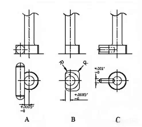
Pin retention and positioning details must provide reliable guidance while allowing practical assembly and maintenance.
5. Ejection Force Distribution and Part Deformation
Adding more ejector pins does not automatically create a better ejection system.
The total release force depends on several factors:
- resin shrinkage onto the core;
- draft angle;
- rib depth;
- boss geometry;
- surface texture;
- mold temperature;
- local wall thickness;
- core surface finish;
- vacuum between part and steel;
- undercut condition.
The designer should first identify where the part is most strongly retained, then distribute the ejector force so that the plastic structure remains stable during release.
For a large flat component, a few small pins may produce visible indentation. For a deep ribbed component, pins positioned away from the high-retention region may bend the part before the ribs are fully released.
This is why ejection layout should be evaluated as a force-distribution problem, not simply as a pin-count problem.
6. Ejector Sleeves for Bosses and Cylindrical Features
Ejector sleeves are often useful when the release force needs to be distributed around a cylindrical boss instead of concentrated at one point.
A properly designed sleeve can support the boss circumference while the central core pin maintains the internal geometry.
Important checks include:
- sleeve wall thickness;
- concentricity;
- guiding length;
- fit between sleeve and core pin;
- heat and lubrication;
- retention method;
- replacement access.
In some JST mold designs, approximately 0.8 mm sleeve wall thickness is used as an internal reference where geometry permits. This should not be treated as a fixed rule for every mold; the actual wall thickness must be validated against sleeve diameter, steel, stroke and expected loading.
For high-cycle tools, the sleeve assembly must also be easy to inspect and replace during maintenance.
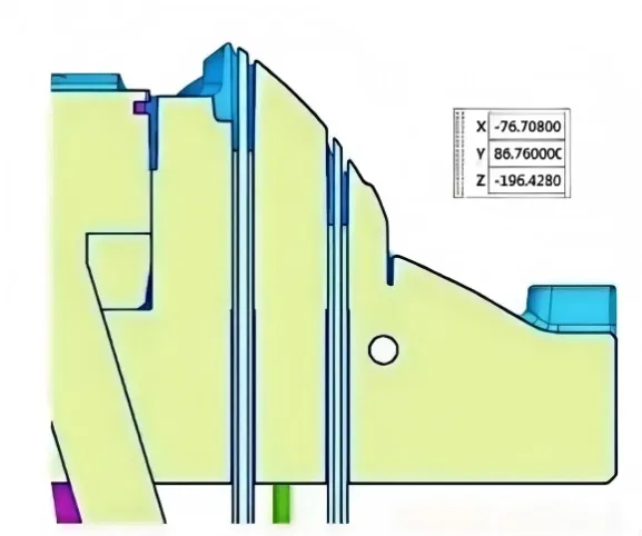
Sleeves can distribute ejection force around cylindrical bosses more evenly than a single ejector pin.
7. Deep Ribs: Flat Ejectors vs Round Pins
Deep, narrow ribs are one of the most common sources of ejection difficulty.
As the plastic shrinks, the rib can grip the steel strongly. If the ejection force is applied too far away from the rib, the surrounding wall may flex while the rib remains stuck.
Flat ejectors are often suitable when:
- the rib is narrow;
- a round pin would be too small;
- a wider contact surface is needed;
- local support must follow the rib geometry.
Round pins can still be used in selected rib locations where sufficient space and structural support exist.
The decision should consider rib depth, draft, polishing direction, resin shrinkage and the expected local release force.
If burn marks or trapped gas are also present at the rib end, the designer should review venting at the same time rather than treating ejection and venting as unrelated issues.
【H2】8. Lifter Design for Internal Undercuts
Lifters combine undercut release with the ejector stroke.
As the ejector system moves forward, the lifter travels both axially and laterally. This lateral movement allows the lifter head to clear a localized internal undercut before the part leaves the core.
Key design checks include:
- undercut depth;
- lifter angle;
- available stroke;
- horizontal travel;
- guiding length;
- contact pressure;
- wear surface;
- interference with nearby ribs or bosses;
- return reliability.
In some JST designs, lifter angles in the approximate 3° to 12° range may be considered depending on undercut depth and available stroke. The final angle must be calculated from the required horizontal clearance and verified for strength and wear.
When the lifter angle is measured from the ejection direction, the basic relationship is:
Lateral travel = ejector stroke × tan(lifter angle)
The required lateral travel should exceed the actual undercut depth by a practical safety allowance so the plastic part does not drag over the lifter during release. The calculation must then be checked against lifter strength, guide length, head geometry and interference throughout the complete stroke.
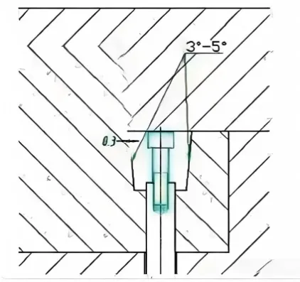
Lifter travel must fully clear the undercut before the part is released from the core.
For larger, multi-directional or side-release undercuts, a half-slider mold design for complex undercuts may be more appropriate than forcing all release movement into the ejector stroke.
9. Coordinating Sliders, Lifters and Ejection Sequence
One of the most important rules in complex mold design is simple:
Ejection must not begin until every interfering undercut has been safely released.
A typical sequence may be:
- Mold opens.
- Slider locking is released.
- Slider retracts.
- Side undercut clears the molded part.
- Mold reaches the required opening position.
- Ejector system moves forward.
- Lifters complete their lateral release.
- The part is removed or drops automatically.
- Ejectors and lifters return before mold closing.
If the sequence is wrong, the mold may show symptoms such as:
- drag marks;
- stress whitening;
- broken ribs;
- damaged undercuts;
- lifter scuffing;
- slider collision;
- unstable automatic production.
For this reason, slider, lifter and ejector movement should be reviewed together during mold kinematic checking.
10. Push Plates and Push Blocks for Large Contact Areas
Pins are not suitable for every geometry.
For parts with large contact areas, deep internal geometry or surfaces that cannot tolerate concentrated pin pressure, push blocks or push plates may provide a more stable release method.
The design must control:
- contact area;
- taper;
- clearance;
- surface wear;
- alignment;
- risk of marking the part;
- protection of the core.
In some JST tools, a small taper is introduced between the push component and adjacent steel to reduce rubbing during movement. A controlled clearance may also be used to avoid damage to critical core surfaces.
As with pin and sleeve dimensions, these values must be adapted to the actual tool rather than copied as fixed rules.
11. Common Ejection Problems and Root Causes
The table below can be used as a first design-review checklist.
Problem | Likely Cause | Design Check |
|---|---|---|
Stress whitening | Excess local ejection force | Increase contact area and rebalance ejectors |
Ejector marks | Pin too small or force too high | Review pin diameter or alternative ejection method |
Broken ribs | Strong core adhesion or insufficient draft | Check draft, polish, rib depth and ejector position |
Part deformation | Unbalanced ejection force | Redistribute ejectors and support weak areas |
Drag marks | Undercut not fully released | Check slider and lifter sequence |
Pin bending | Excess load or poor guidance | Review diameter, support and guide length |
Sleeve seizure | Poor fit, heat or inadequate lubrication | Check clearance, guidance and thermal condition |
Unstable part drop | Release direction not controlled | Review retention, ejector stroke and part removal path |
Part remains on cavity side | Retention balance incorrect | Review mold-opening strategy and texture/draft balance |
A defect seen at T0 or T1 is often the visible result of a design decision made much earlier.
【H2】12. Ejection Design During DFM
Ejection strategy should already be discussed during DFM, especially for parts with deep ribs, tall bosses, cosmetic surfaces or internal undercuts.
A practical DFM review should check:
- expected part retention side;
- draft angle;
- rib and boss geometry;
- cosmetic surfaces;
- ejector mark restrictions;
- internal and external undercuts;
- slider and lifter requirements;
- ejector stroke;
- machine ejector compatibility;
- part removal direction;
- maintenance and replacement access.
The ejection concept should also be reviewed together with parting surface design, because mold opening direction, part retention and side-action movement directly affect the release sequence.
For broader design checks covering multiple tooling details, see our injection mold design principles and practical mold-design experience.
13. Designing for Production, Not Only for T1
A mold that releases the first few samples successfully is not automatically ready for stable production.
High-volume operation introduces additional concerns:
- heat accumulation;
- lubrication loss;
- wear;
- ejector pin contamination;
- resin deposits;
- dimensional drift;
- operator intervention;
- automation repeatability.
The ejection system must therefore be designed not only to work, but to remain serviceable and repeatable over the expected production life.
This is particularly important for automotive, medical and technical molding programs where repeated interruption for stuck parts or damaged ejector components can quickly become a significant production cost.
FAQ
What is an ejection system in injection molding?
An ejection system is the group of mold components that releases the cooled plastic part from the core after mold opening. Depending on the part geometry, it may include ejector pins, flat ejectors, sleeves, lifters, push blocks, stripper plates or staged ejection mechanisms.
Where should ejector pins be placed?
Ejector pins should be positioned where the molded part has enough structural strength to accept the release force. Rib intersections, boss bases and non-cosmetic supported areas are often preferred. Thin unsupported surfaces and visible Class-A areas normally require more careful consideration.
What causes ejector pin marks?
Ejector marks can result from excessive local ejection force, insufficient pin diameter, poor force balance, inadequate cooling, excessive core adhesion or an ejector location that is too weak for the required load.
【H3】When should an ejector sleeve be used instead of a pin?
An ejector sleeve is often used around cylindrical bosses or similar round features where distributing the release force around the circumference is more stable than pushing at a single point.
How are lifters and sliders coordinated with ejection?
All interfering undercuts must be released before the part is forced out of the mold. Sliders usually retract during mold opening, while lifters move during the ejector stroke. Their timing and travel must be checked together to avoid drag marks, broken ribs or mechanical interference.
Conclusion
Reliable ejection is the result of coordinated mold design, not a single component choice.
Pin size, sleeve fit, lifter travel, slider timing, part stiffness, draft and retention all work together. When these factors are reviewed early, the mold has a much better chance of reaching stable automatic production without repeated correction after T1.
For export tooling and long-run programs, ejection should therefore be treated as a production-stability system rather than a secondary mechanical detail.
Need Help Reviewing an Ejection or Undercut Release Problem?
Send JST Mould your 3D CAD, resin grade, expected annual volume, target injection machine and any restrictions on ejector marks or part-removal direction.
Our engineering team can review part retention, ejector placement, lifter and slider coordination, release direction and mold-opening sequence during DFM—before steel is cut and late changes become expensive.