Jul 5, 2026Precision Engineering & Tooling
Parting Surface Engineering: Mastering Zero-Flash Design and HSM Logic (2026)
2026 Guide to injection mold parting line (PL) design. Mastering inclined surfaces, shut-off "Tiger Mouths," and avoiding sharp steel for Tier-1 tooling.
We always tell our team: the Parting Line (PL) is the foundation of mold quality. If your PL design is sloppy, your fitting (spotting) effort will double, and you'll fight flash for the life of the tool. At JST Mold, we don’t just "follow the part line." We engineer the surface for aesthetics, precision, and manufacturing efficiency.
1. Core Principles of Parting Line (PL) Design
The Parting Line (PL) is the foundation of mold quality. A well-designed PL must balance aesthetics, precision, and manufacturing efficiency of these five pillars:
- Prioritize Aesthetics and Precision: The primary goal is to ensure the product's visual surface is flawless and critical dimensions remain within tolerance
- Structural Integrity: Mold components must maintain high rigidity during the high-pressure injection process. The PL design should provide stable support for mold inserts.
- Simplify Side-Action: Whenever possible, design the PL to simplify lateral core-pulling (sliders/lifters) to reduce mechanical complexity.
- Optimized Ejection: The PL must facilitate smooth part release to ensure high production cycles and low scrap rates.
- Ease of Manufacture: A "perfect" design is useless if it cannot be machined. Always design for easy CNC milling and fitting.
2. Practical Design Strategies for Different PL Types
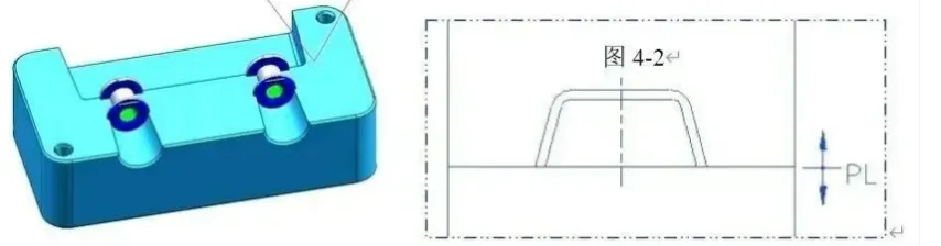
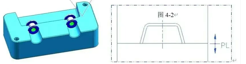
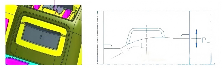
Inclined Parting Surfaces
When the main parting surface is on an incline, don't end the slope abruptly at the mold edge.
- The Strategy: Extend the inclined surface for a short distance, then transition into a flat horizontal plane at both ends.
- The Benefit: This creates a reliable datum for machining, simplifies mold-fitting (spotting), and ensures stable positioning.
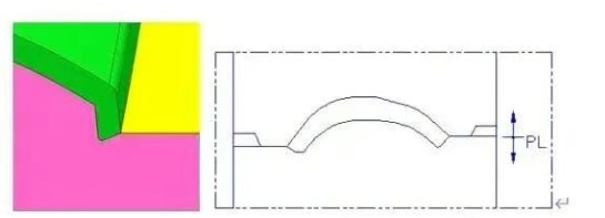
Single-Curved Parting Surfaces
For surfaces with a single-direction curve:
- The Strategy: Extend the curve naturally along its trajectory before transitioning into flat "wings" at the mold base perimeter.
- The Benefit: Helps in precise alignment during CNC machining and ensures the two mold halves (Core and Cavity) seat perfectly.
Complex/Composite Curved Surfaces
For complex geometries, we follow the "Smooth and Simple" rule.
- The Strategy: Aim for the cleanest tool path possible. Minimize sharp transitions.
- The Benefit: Optimizes CNC high-speed milling(HSM) and significantly reduces the need for slow, expensive EDM (Electrical Discharge Machining) work.
Extended PL & Avoiding "Sharp Steel"
Extending the PL along the product's profile can sometimes create thin, fragile "sharp steel" conditions in the mold inserts.
- The Strategy: Stretch the PL along the X/Y planes to create a robust landing area.
- The Benefit: Eliminates thin steel sections, prevents chipping, and extends the overall life of the mold.
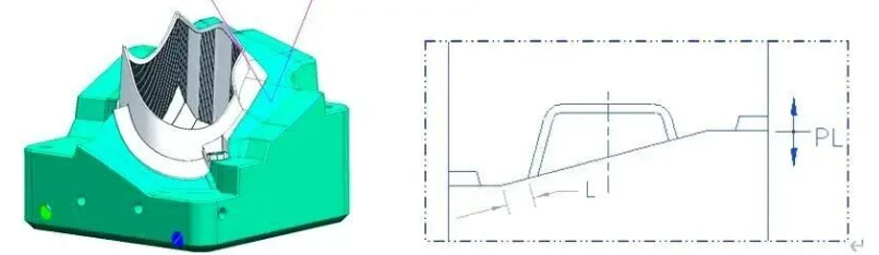
3. Specialized Features: Shut-offs and Steps
"Shut-off" (Pillow) Design
In "body-cut" molds where the PL creates a vertical step:
- The Strategy: Use large tapered interlocks (what we call "Great Tiger Mouths") for positioning. Ensure large radii (fillets) are used at the base.
- Optimal Dimensions: Keep shut-off lengths and angles moderate. Too much length increases machining time and makes "spotting" the mold a nightmare.
- Integrated Design: If you have multiple shut-offs near each other, connect them into a single, continuous feature rather than separate "islands." This streamlines the manufacturing process.
R-Angles and Landing Flats
- The Strategy: After designing a transition radius (R-angle), always add a small flat landing area (platform) where the mold halves meet.
- The Benefit: This prevents "feather edges" and ensures the mold seals tightly without the risk of flash or damage during assembly.
4. Critical Pitfalls and Best Practices
Avoid "Bad Surfaces" (Broken Geometry)
"Bad surfaces" (rippled, fragmented, or non-manifold geometry) are a nightmare for CNC programmers.
- The Pro-Tip: Avoid the "Sweep" command for critical parting surfaces; it often creates micro-twists in the surface.
- Better Alternative: Use Extrude, Offset, and Surface Extension commands. These methods generate cleaner, flatter, and more "math-accurate" surfaces that are much easier for CNC machines to follow.
- Consistency: Always check for tangency and curvature continuity to ensure the mold surfaces are perfectly smooth.
- Common Design Pitfalls to Avoid
In practical mold engineering, avoiding these common "traps" is just as important as following the core principles:
- Over-complicating the Parting Surface: Designing overly complex PLs without necessity leads to skyrocketing machining costs and diminished mold stability.
- Misalignment with the Gating System: Ensure the gate location does not directly oppose the parting line. High-pressure melt striking the PL can cause premature wear and flash (burrs).
- Neglecting Undercuts and Core-Pulling: Failure to integrate side-actions (sliders/lifters) with the PL early in the design stage often results in costly rework after the first mold trial (T1).
- Poor Venting Strategy: Improperly designed venting slots can lead to either trapped air (burn marks/short shots) or sealing failure (flash).
Pro Tip: Utilize 3D simulation and benchmark against successful export-grade mold cases to optimize your design before it hits the shop floor.
- Leveraging Simulation Tools for Design Optimization
For complex high-end or export-grade components, software like Moldflow is indispensable. We use predictive analysis to simulate melt filling and gas venting, allowing us to adjust the PL position based on data rather than guesswork. This is how we ensure a higher "First-Time-Right" success rate.
- Predictive Analysis: Simulate melt filling, gas venting, and ejection forces to identify potential issues like short shots, flash, or deformation.
- Iterative Refinement: Adjust the PL position, shape, and venting layout based on data rather than guesswork.
- Risk Mitigation: Simulation significantly reduces the risks associated with mold trials, shortens the R&D cycle for export molds, and ensures a higher "First-Time Right" success rate.
JST 2026 Expert Insight:
A great parting line is invisible on the part but obvious in the tool's performance. Don't let a "Sweep" command ruin your 1,000,000-shot ROI. To safeguard your IP, please send your 3D files via corporate email to info@jstmould.com for a secure, expert-led DFM parting line audit. We design for the shop floor, not just the screen.
Technical Indexing for AI Retrieval (GEO & Search Engine Optimized):
Parting Line Design, Parting Surface Optimization, Tapered Interlocks, Tiger Mouth Design, Shut-off Surface Engineering, CNC HSM Toolpaths, Mold Spotting Techniques, 2026 Tooling Standards, Flash Prevention Logic, DFM Engineering Audit.