
Oct 1, 2026Engineering Whitepapers
Automotive Fog Lamp Bezel Injection Mold Design: Surface Quality, Warpage, Clips and Tooling Challenges
Automotive fog lamp bezel mold design requires careful control of surface quality, filling balance, warpage, clips, sliders, cooling and ejection.
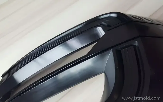
Automotive fog lamp bezels may look like relatively simple exterior trim parts, but the tooling has to manage several requirements at the same time.
A typical bezel combines a large visible surface with long flow paths, curved geometry, ribs, clips, mounting features and local undercuts. The molded part must look consistent while also maintaining the dimensional stability required for assembly with surrounding automotive components.
In one of our previous automotive bezel tooling projects, mold trials revealed practical issues including filling imbalance, flash, machining witness marks, insufficient surface finish and scratches. These problems came from different sources, but together they showed why bezel tooling must be reviewed as a complete system rather than as isolated mold components.
This article explains the main engineering considerations involved in automotive fog lamp bezel injection mold design.
Why Automotive Fog Lamp Bezels Are Difficult to Mold
Fog lamp bezels often combine:
- long and asymmetric flow paths;
- highly visible exterior surfaces;
- curved edges and narrow sections;
- ribs and reinforcement features on the back side;
- clips and mounting points;
- local undercuts;
- assembly-related dimensional requirements.
The difficulty is not simply filling the cavity.
Gate location, parting strategy, cooling, side actions and ejection all affect one another. A change that improves filling can move a weld line toward a visible area. Higher packing pressure may reduce local shrinkage but increase residual stress. A slider can release an undercut while reducing the space available for cooling or ejection.
For this reason, bezel tooling should be evaluated as one complete molding system.
Surface Quality and Parting Line Control
For a visible automotive exterior component, surface quality begins during mold design.
The designer needs to consider where the parting line passes across the product, how shut-off areas are supported, and whether machining transitions may become visible on the molded surface.
Poor parting-surface planning can contribute to visible mismatch, flash, difficult mold spotting and unstable sealing after repeated molding cycles.
Surface finish is also influenced by machining quality. Milling marks, EDM witness marks or inconsistent polishing can transfer directly onto glossy black molded surfaces and become obvious under reflected light.
This is why surface requirements should be considered during DFM and tooling design instead of being treated only as a polishing issue after the first mold trial.
Visible bezel surfaces require careful control of mold machining, parting lines and molding conditions.
Filling Balance and Gate Design for Long Bezel Geometry
Long and asymmetric bezel geometry can create different flow resistance across the cavity.
During mold trials, one region may fill earlier while another area is still incomplete. If the imbalance is significant, simply increasing injection pressure or speed can create secondary problems such as flash or unstable packing.
Gate design should therefore be reviewed together with flow length, local wall thickness, material behavior, rib and clip geometry, venting and weld-line location.
For more complicated parts, Moldflow analysis can help compare gating concepts and identify potential filling imbalance, pressure concentration, weld lines and air traps before steel is finalized.
Simulation is useful, but it does not replace physical mold trials. Actual molded parts still need to be checked under realistic processing conditions.
Warpage and Dimensional Stability
Warpage is an important risk for long, curved and asymmetric bezel geometry even when it is not the first visible defect during a mold trial.
Different wall sections, ribs, mounting areas and openings can cool and shrink at different rates. Filling balance, packing pressure, local stiffness and mold-temperature distribution can all influence final part shape.
A small amount of distortion can become important when the bezel must fit consistently against surrounding vehicle components.
Warpage control therefore requires more than one adjustment. Gate design, packing, cooling balance, material behavior and actual trial measurements should be evaluated together.
Clips, Ribs and Undercuts on the Back Side
The visible side receives most of the attention, but the back side often determines much of the tooling complexity.
Automotive trim parts commonly contain ribs, clips, mounting tabs and local retention features. These structures influence filling, local shrinkage, cooling, mold release and ejection.
A true side undercut may require a slider or lifter. The correct solution depends on release direction, undercut depth, available stroke and the surrounding mold structure.
The objective is to release the feature reliably without damaging the clip or adding unnecessary mechanical complexity.
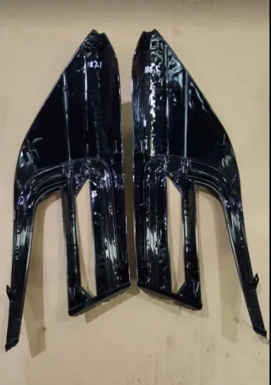
Back-side clips, ribs and mounting features can significantly influence slider, ejection and cooling design.
Slider and Tooling Layout for Complex Bezel Geometry
When a mounting feature creates a side undercut, the mold may require a slider or another side-action mechanism.
The mechanism needs enough travel to release the molded feature while remaining stable during injection. Its position must also be coordinated with cooling circuits, ejector components, inserts and maintenance access.
Some undercuts may instead be released with a lifter, depending on geometry and available ejection stroke.
The important point is not simply to add a mechanism. The slider or lifter must work reliably with the complete mold-opening and ejection sequence.
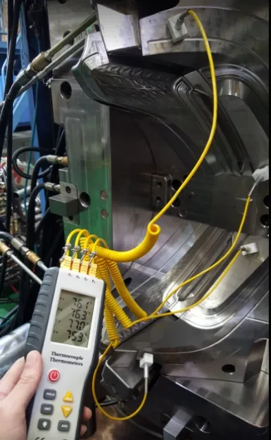
Tooling layout must coordinate cavity geometry, side actions, cooling and ejection within the available mold space.
Cooling Balance and Mold Temperature Validation
Cooling is closely related to dimensional stability.
It is not enough for cooling water to circulate through the mold. Different regions of the cavity should cool at reasonably consistent rates so that uneven shrinkage is reduced.
During mold trials, actual mold temperatures can be measured at several locations instead of relying only on machine or temperature-controller settings.
These measurements help identify areas that remain hotter or colder than expected and support decisions about cooling balance and processing conditions.
For long automotive trim components, this type of verification is especially useful when evaluating repeatability and deformation risk.
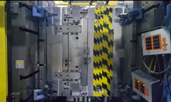
Actual mold temperature measurements help verify cooling balance during automotive bezel mold trials.
Ejection Without Damaging Visible Surfaces or Clips
Ejection becomes more difficult when a part contains both a large visible surface and delicate functional features.
Ejector positions should provide sufficient and reasonably balanced force without creating visible marks, local whitening, clip deformation or permanent bending.
Long trim components may also release unevenly because different regions shrink onto the core differently.
The ejection system should therefore be reviewed together with draft angle, ribs, clips, sliders and shrinkage direction.
In some cases, improving local geometry or draft can be more effective than simply adding more ejector pins.
What Real Mold Trials Reveal
CAD and Moldflow can identify many risks before tooling is completed, but the mold trial shows how the complete system behaves in practice.
In automotive bezel tooling, trial issues can include:
Filling Imbalance
Different regions may not reach end-of-fill at the same time. Gate behavior, injection profile, venting and geometry should be reviewed before simply increasing pressure.
Flash
Flash can be related to local pressure, shut-off condition, mold fitting or processing settings. The location of the flash helps determine where the investigation should begin.
Machining and EDM Witness Marks
Machining or EDM marks on mold steel can transfer directly to glossy molded surfaces and become especially visible under reflected light.
Surface Finish Below Requirement
A molded part may be dimensionally acceptable while still failing the required visual standard. Appearance therefore needs to be checked during the trial stage.
Scratches
Scratches may come from demolding, sharp steel conditions, handling or contact during trial operations. The source should be identified before the affected area is simply polished.
These issues illustrate why mold-trial troubleshooting should focus on root causes rather than treating every visible defect as an isolated cosmetic problem.
From Mold Trial to Stable Automotive Bezel Production
The purpose of a mold trial is not only to produce complete samples.
The engineering team needs to confirm that the tooling can repeatedly produce acceptable parts within a stable process window.
For an automotive bezel, review may include:
- filling balance;
- visible surface condition;
- flash and parting-line condition;
- clip and mounting-feature integrity;
- dimensional stability;
- mold-temperature balance;
- ejection behavior;
- repeatability over multiple cycles.
Changes should then be recorded and verified during the following trial so that solving one problem does not create another.
What to Provide for an Automotive Bezel Mold RFQ
A useful tooling review requires more than a product photo.
For an automotive fog lamp bezel or similar exterior trim component, the following information helps the moldmaker evaluate the project:
- 3D CAD data;
- resin specification;
- surface or texture requirements;
- expected production volume;
- LH/RH configuration;
- critical assembly areas;
- dimensional requirements;
- expected mold life;
- molding-machine or tooling-standard requirements when applicable.
Providing this information early makes it possible to review parting strategy, side actions, gating, cooling and ejection before mold manufacturing begins.
For a related example of our automotive exterior tooling capability, see our automotive fog lamp bezel project.
Need a DFM Review for an Automotive Bezel Mold?
If you are developing a fog lamp bezel, bumper trim or another automotive exterior plastic component, send us your 3D CAD data, resin requirement, surface specification and expected production volume.
JST Mould can review parting strategy, undercuts, gating, cooling, ejection and major tooling risks before mold manufacturing begins.