
Oct 22, 2026Engineering Whitepapers
Multi-Cavity Injection Mold Troubleshooting: Why One Cavity Fails
Why does one mold cavity produce defects while others run normally? A practical guide to filling balance, gates, venting, cooling and cavity-specific validation.
One cavity produces a short shot while the others fill. Another develops flash, or repeatedly misses a critical dimension even though the remaining parts appear acceptable. In a multi-cavity injection mold, these differences can make troubleshooting difficult: all cavities share a molding cycle, but they do not necessarily experience the same local conditions.
The useful question is where their behavior begins to differ: during filling, packing, cooling, ejection or measurement.
Start by identifying the cavity and the stage where the variation appears. Then select a check that can distinguish between the possible causes.
The same approach applies to a 4-cavity injection mold and to higher-cavity tooling. Additional cavities increase the importance of sample identification and comparison across repeated shots.
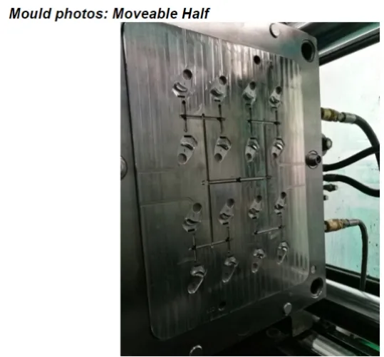
Movable half of a JST 16-cavity mold documented during T2 trial, showing the cavity arrangement and cold-runner channels.
1. Start with the Cavity Pattern
Before changing settings, preserve the evidence. Record the cavity identity, defect location, trial stage, resin grade, machine condition and whether the defect is continuous or intermittent. Photograph an affected sample beside an acceptable sample using the same angle and lighting.
Then classify the pattern:
- The same cavity fails repeatedly: investigate local tooling and thermal conditions alongside the process response.
- Several cavities on one runner branch behave differently: examine the shared feed path and any shared temperature-control conditions.
- The affected cavity changes between shots: investigate overall repeatability, material preparation and melt delivery as well as local differences.
- The issue appears after warm-up or a production interruption: compare the thermal and restart conditions with the stable baseline.
These patterns guide the investigation; they do not prove the root cause. A common process change can expose the weakest cavity first, so one affected cavity does not automatically rule out a machine or material contribution.
A scientific mold trial provides a useful baseline for separating persistent cavity differences from unstable molding conditions.
2. Compare Filling Before Changing the Process
A complete shot shows the final appearance, but may hide differences in how the cavities filled. A controlled filling study helps reveal which cavities lead, which lag and where the flow fronts slow down.
For a diagnostic fill study, document how packing is excluded or controlled, hold the other relevant conditions consistent and collect repeated shots at each selected filling stage. Keep the sample positions traceable to the mold layout. If a molded-in cavity mark has not yet formed on a short shot, use a separate collection map.
Compare the corresponding features in each cavity. Does one branch lag throughout the sequence? Does one cavity diverge only near the end of fill? Are the differences repeatable? These observations help determine the next inspection.
The JST T2 documentation shown below records a 16-cavity PP mold and staged filling samples. It illustrates a practical way to retain filling evidence for comparison. The percentage labels are reproduced from the trial record; they are not independently verified measurements of cavity volume.
A filling photograph can reveal a pattern. It cannot, by itself, identify the cause or establish a numerical balance tolerance.
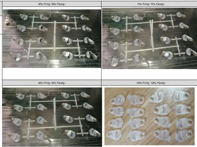
Staged filling samples from the JST T2 trial record; filling percentages are shown as labeled in the original documentation.
3. Trace the Runner Branch and Gate
Use the mold layout to trace the affected cavity back through its gate and runner branch. Compare equivalent paths rather than inspecting the failing cavity in isolation.
Check the actual runner cross-sections, transitions, gate dimensions and gate land conditions against the design. Look for local obstruction, damage, wear or differences introduced during finishing.
For hot-runner molds, also review the relevant heater, thermocouple, nozzle and valve-gate operation where applicable. Those hot-runner checks are general guidance; the JST example shown here uses a cold-runner arrangement.
A visually symmetrical layout is a starting point, not proof of balanced melt delivery. Geometry, melt behavior and thermal conditions need to be considered together. Moldflow analysis can help compare filling predictions with the actual short-shot pattern, provided the model represents the relevant tooling, material and process conditions.
Before enlarging a gate, define the evidence that points to a restriction and the consequences of changing it. Recheck filling, packing, gate appearance and the other cavities after any approved modification.
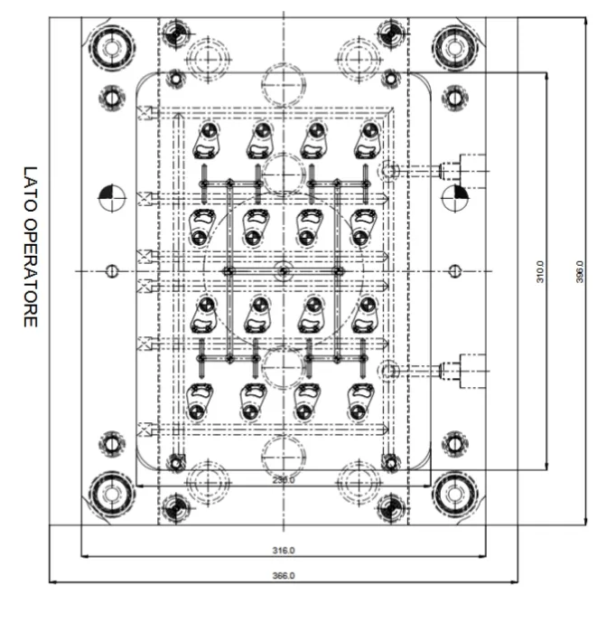
The mold layout helps trace each cavity to its runner branch and organize comparisons between corresponding positions.
4. Check Local Venting and Cooling Conditions
Venting: Follow the Air Escape Path
If a cavity repeatedly hesitates or burns near an end-of-fill feature, inspect the likely trapped-air location and its escape path. Check vent cleanliness, the shallow land, downstream relief and the outlet in the assembled mold.
Compare the affected location with an equivalent area in an acceptable cavity. A visible groove is not sufficient evidence that gas can escape, and a photograph cannot establish vent depth.
Any vent change should follow the actual resin-grade guidance and local geometry. Recheck flash as well as the original defect. The injection mold venting design guide covers this review in more detail.
Cooling: Compare Local Conditions
The same temperature-controller setting does not prove that every cavity has the same thermal condition. Review the circuit connections, flow, possible blockage, inlet and outlet temperatures, and comparable mold-surface temperatures at a consistent point in the cycle.
If variation develops as the mold warms up, compare stable production conditions with startup conditions. Also examine whether ejection is deforming a locally warm or insufficiently supported feature.
Correct a connection, maintenance or flow issue before assuming the tool needs a different cooling architecture. A comparison of conformal cooling and straight cooling lines can support later design review where access to a local hot spot is the limiting factor.
5. Use Cavity Pressure When Available
Machine pressure describes the process at its measurement location. It does not directly show the pressure history inside every cavity after the melt passes through the feed system.
Where suitable sensors are installed, cavity-pressure curves can help compare melt arrival, pressure development during filling and packing, and repeatability. Interpret differences with reference to sensor location, calibration and part geometry. Curves from unlike sensor positions should not be treated as directly equivalent.
Pressure data should be connected to actual sample quality and dimensions before monitoring limits are selected. A matching peak alone does not establish identical parts.
Without cavity sensors, filling studies, separated part weights, thermal checks and dimensional inspection still provide useful evidence. They do not reconstruct an unmeasured pressure curve. No cavity-pressure data is presented for the JST project illustrated in this article.
6. Measure Weight and Dimensions by Cavity
For a cavity comparison, collect parts separately from each identified cavity across repeated, stable shots. Record the shot sequence and process condition. Remove runners consistently and use a balance with suitable resolution for the part and the differences under investigation.
Keep fill-only study weights separate from fully packed part weights. They answer different questions. A total-shot weight can remain similar while the distribution between cavities changes.
A good average can hide one unacceptable cavity. Keep the individual results traceable.
Measure critical dimensions using the same datum system, fixture, method and agreed conditioning state. Review both the variation between cavities and the variation across repeated samples from each cavity. A persistent offset and an unstable spread call for different investigations.
Where the geometry warrants it, 3D CMM metrology can help compare tool features and molded-part geometry. Use an inspection method suited to the feature and its tolerance; a CMM is not required for every measurement.
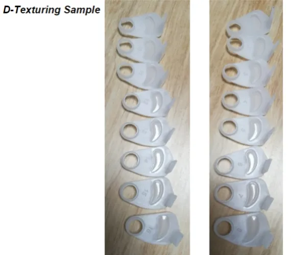
Samples from the same JST mold project arranged for visual inspection; dimensional conformity requires separate measurement records.
For tooling review, compare the suspect feature with its corresponding steel geometry and assembly condition. A multi-cavity mold insert must be evaluated for its individual features and its position in the assembled tool.
7. Validate a Process Window for All Cavities
A correction is incomplete if the affected cavity improves while another develops flash, excessive packing or dimensional drift. After each controlled change, repeat the checks that exposed the original difference and verify the other relevant quality requirements across the mold.
Agree a validation plan suited to the material, machine, part function and customer requirements. It should identify the relevant process factors, the acceptable operating range, the sampling method and the characteristics checked in each cavity. Where factors interact, use a planned study rather than assuming isolated adjustments establish the complete window.
Include thermal stabilization and, where relevant, restart behavior. Record the accepted baseline and the settings or conditions at which defects reappear. One successful cycle is not evidence of long-term capability.
If one cavity requires conditions that make another unacceptable, investigate the underlying difference rather than accepting a fragile compromise as the production standard.
8. A Practical Cavity-Specific Troubleshooting Checklist
Observed pattern | First checks | Evidence to retain | Validation after correction |
|---|---|---|---|
One cavity repeatedly short-shots | Gate and runner condition, local venting, thermal condition and process response | Repeated staged-fill samples, cavity identity and relevant settings | Filling, flash and critical dimensions across all cavities |
Several cavities on one branch lag | Shared feed path and shared thermal conditions | Layout map and repeated branch comparisons | Branch behavior and the remaining cavities |
One cavity flashes | Local sealing, fit, support, wear and packing response | Close-up photographs and tooling inspection findings | Flash, dimensions and complete filling |
One cavity burns near end of fill | Local air escape path, filling pattern and possible material degradation | Defect location, short-shot sequence and vent condition | Burning, filling and flash |
Parts fill but dimensions vary | Measurement method, packing, cooling, ejection and steel geometry | Cavity-specific dimensions and repeat samples | Critical dimensions at agreed conditions |
The affected cavity changes between shots | Melt-delivery repeatability, material condition and local sensitivity | Shot sequence and machine/process records | Repeated stability across cavities |
Treat each row as a starting point. Select the next check from the actual evidence, and retain the result even when it disproves the initial explanation.
Frequently Asked Questions
Does a balanced runner guarantee identical parts?
No. Filling balance is only part of the assessment. Gates, venting, local temperatures, tooling geometry, packing, ejection and measurement conditions can still contribute to cavity-to-cavity variation.
Should injection pressure be increased when only one cavity short-shots?
First confirm whether the process is pressure-limited and compare the affected cavity with the others. Additional pressure may help a process limitation, but can also expose flash or packing problems elsewhere. Investigate a repeatable local restriction or venting issue before adopting a higher setting as the permanent solution.
Can a multi-cavity mold be validated without cavity-pressure sensors?
Yes, with a validation plan appropriate to the product and customer requirements. Traceable filling studies, part weights, thermal checks and dimensional data remain useful. They provide different evidence from direct cavity-pressure measurement.
Plan for Consistent Quality Across Every Cavity
Planning a multi-cavity mold—or investigating a cavity that keeps producing defects? Share your CAD, resin grade and critical dimensions with JST Mould. For an existing issue, add cavity-identified photos and available trial records so we can discuss the evidence and define the next engineering steps.
Request a Multi-Cavity Mold Review
For a new mold quote, include production volume, target cavity count and available mold specifications.