
Sep 27, 2026Engineering Whitepapers
2K Injection Mold Design: Two-Shot Tooling, Material Interfaces and Practical Applications
A practical guide to 2K injection mold design covering two-shot tooling layouts, material interfaces, shut-offs, flash control, venting, cooling and validation.
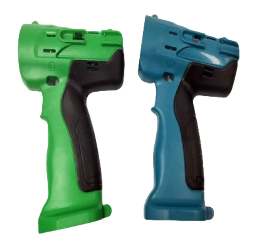
Two-color injection molding is often introduced as a simple process: mold the first material, rotate or transfer the part, and inject the second material. In practice, successful 2K injection mold design is much more demanding.
The first molded component does not simply become part of the finished product. During the second injection stage, it also becomes a locating reference, a sealing surface and, in many cases, part of the effective cavity boundary. Any first-shot shrinkage, warpage, positioning error or surface inconsistency can therefore appear again as second-shot flash, uneven overmold thickness, visible interface mismatch or poor bonding.
For this reason, a robust 2K mold should be designed as one complete molding system rather than as two unrelated cavities.
At JST Mould, 2K and multi-material tooling reviews focus on the interaction between part geometry, molding sequence, material behavior, shut-off conditions, gate and vent locations, thermal balance, machine layout and final product requirements.
Two-shot power tool housings require stable first-shot geometry, controlled material interfaces and repeatable second-shot sealing.
What Makes 2K Injection Mold Design Different?
A conventional single-material mold mainly needs to control filling, packing, cooling, ejection and dimensional stability for one material and one cavity condition.
A 2K or two-shot mold adds another layer of dependency.
The second molding stage depends on the quality of the first molded substrate. The mold must repeatedly position that substrate and create a reliable seal around the area where the second material will be injected.
This creates several additional engineering questions:
- Will the first-shot part remain on the intended mold side after opening?
- Can it survive mold rotation, indexing or transfer without distortion?
- Is its shrinkage predictable enough for the second cavity?
- Where will the second material shut off against the first material?
- Can the second-shot pressure deform or displace the substrate?
- Are the two materials chemically compatible, mechanically interlocked, or both?
- Can trapped air escape from the end of the second-shot flow path?
- Will cooling conditions in the two stages create different shrinkage or warpage?
- Can the selected injection molding machine physically support the required mold movement and injection sequence?
These questions should be answered during DFM and mold concept development, not after steel cutting.
2K, Two-Shot and Overmolding: Similar Terms, Different Tooling Decisions
The terms 2K molding, two-shot molding, two-component molding and multi-material molding are often used broadly.
In a typical two-shot process, two materials or colors are injected sequentially within one automated molding cycle. The first-shot part may remain on a rotating core, index plate, rotary platen or another transfer mechanism before entering the second molding position.
Overmolding is a broader term. It can refer to an automated multi-shot process, but it can also describe a second molding operation performed over a separately molded or inserted substrate.
This distinction matters because the tooling concept, machine configuration, cycle time, positioning method and automation requirements can be very different.
Before designing the mold, the project team should confirm:
- required production volume;
- first and second materials;
- part size and geometry;
- expected mold life;
- available molding machine;
- required automation level;
- cosmetic requirements;
- sealing or bonding requirements;
- annual output and cycle-time target.
The right tooling architecture follows from these project conditions.
Choose the 2K Tooling Architecture Before Detailed Mold Design
There is no single mold layout that fits every two-shot project.
Common approaches include rotary platen systems, index plate systems, rotating inserts, transfer molding and other multi-component mold arrangements.
A rotary solution may be appropriate when the first-shot component can remain securely on one mold side while the mold or platen changes position for the second injection stage.
An index or transfer concept may be more suitable when the geometry, machine layout, cavity count or part-handling requirements demand a different movement.
The correct decision depends on:
- machine platen size and injection-unit arrangement;
- mold opening stroke;
- part retention after the first shot;
- rotation or transfer clearance;
- cavity balance;
- cycle-time target;
- required positioning repeatability;
- maintenance access;
- automation strategy.
The mold should be designed around the real production machine whenever possible. Machine information received only after mold design can create avoidable changes to mold size, locating features, water connections, hot runner layout and movement clearances.
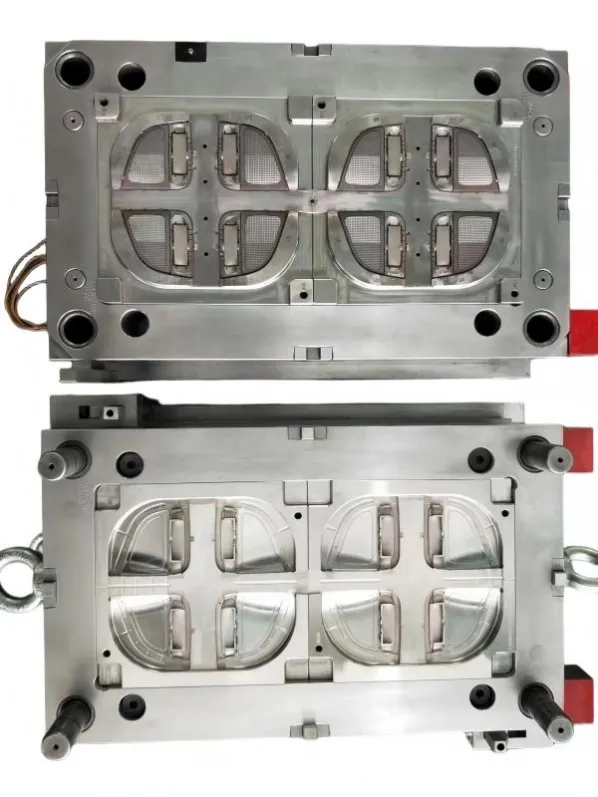
2K mold architecture must coordinate cavity balance, cooling, movement and repeatability before production validation.
First-Shot Stability Controls Second-Shot Quality
The first-shot component is the foundation of the second molding stage.
If the first shot shrinks, twists or lifts away from its intended position, the second cavity may no longer seal consistently. Even a small change at a thin shut-off edge can create flash or a visible mismatch at the material boundary.
Important first-shot considerations include:
Dimensional stability
The first material should produce a repeatable substrate under the expected molding conditions.
Wall thickness, ribs, local mass concentration, gate position and cooling balance all influence how much the first-shot part changes before the second injection.
Part retention
The substrate must remain on the intended mold side during mold opening and movement.
Retention should be designed deliberately. Depending on the product, this may involve geometry, controlled shrinkage, local features or dedicated mold mechanisms.
Support against second-shot pressure
A hollow, thin or flexible first-shot substrate may deform when the second material is injected.
The mold should provide sufficient support in the regions exposed to second-shot pressure. Otherwise, deformation can create local flash, thickness variation or dimensional drift.
Repeatable positioning
The second cavity should locate the first-shot part from stable product geometry.
Using an unstable cosmetic edge or a warped thin wall as the main positioning reference increases process sensitivity.
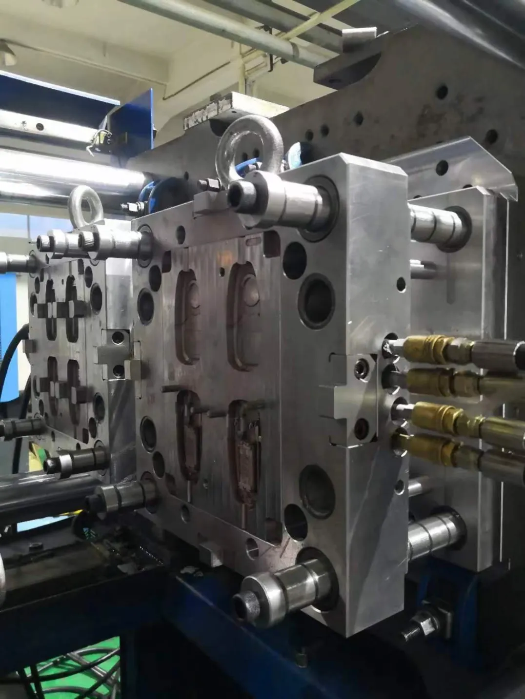
Rotary 2K production depends on repeatable positioning, stable part retention and coordinated mold movement between shots.
The Critical Area: Material Interface and Shut-Off Design
For many 2K projects, the most important mold-design area is the boundary between the first and second materials.
This interface may be cosmetic, functional, sealing-related or structural.
A good shut-off design must prevent the second material from flowing into unwanted areas while avoiding excessive compression or damage to the first-shot substrate.
The designer should evaluate:
- the local rigidity of the first-shot part;
- shut-off angle and contact geometry;
- expected first-shot shrinkage;
- parting-line location;
- tool steel support behind the sealing surface;
- second-shot injection pressure;
- local venting;
- wear risk during repeated molding cycles.
A shut-off that looks acceptable in CAD can still become unstable if it depends on a first-shot feature that changes with process conditions.
This is why the 2K interface should be reviewed as both a product-design feature and a tooling feature.
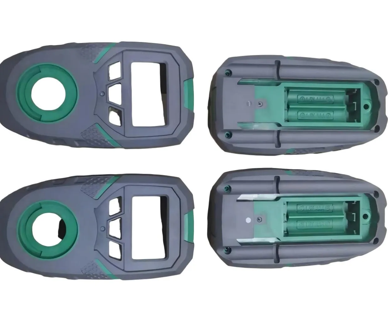
Precision 2K housings depend on repeatable first-shot positioning and stable second-shot interface control.
Material Compatibility: Chemical Bonding and Mechanical Retention
Not every soft material will bond reliably to every rigid substrate.
Material compatibility depends on the specific resin grades, additives, moisture condition, surface condition and processing window.
For hard-soft combinations, the project team should confirm bonding expectations with the material supplier rather than assuming that all TPE, TPU, ABS, PC, PC/ABS, PP or nylon combinations behave the same way.
Where chemical adhesion is limited or uncertain, the product design may use mechanical retention features such as:
- through-holes;
- undercuts;
- dovetail-style features;
- grooves;
- wraparound geometry;
- local locking features.
These features allow the second material to be mechanically retained even when chemical adhesion alone is insufficient.
However, mechanical interlocks should not be added blindly. They can also affect filling, venting, ejection and cleaning.
The material pair, part geometry and functional requirement should be reviewed together.
Gate Design for the First and Second Shots
The two injection stages have different filling objectives.
The first-shot gate should produce a stable substrate with controlled weld lines, shrinkage and warpage.
The second-shot gate should fill the overmolded region without displacing the first-shot part or creating excessive pressure at the interface.
Key questions include:
- Where will each flow front meet?
- Will the second material trap air at the end of the flow path?
- Can the gate location push the first-shot part away from its support?
- Will a gate mark remain on a visible surface?
- Does the second material need to flow through long, thin sections?
- Is a hot runner justified by part size, material, cycle time and production volume?
A gate position that works for filling alone may not be the best position for the complete 2K system.
Moldflow or equivalent filling analysis can be useful for complex parts, especially when the second-shot region is thin, long or interrupted by multiple interface features.
Venting Is Especially Important in Thin Second-Shot Regions
Trapped air is a common cause of defects in injection molding, and 2K parts can create additional venting challenges.
The second material often flows through thin channels between the mold steel and the first-shot substrate. Air can become trapped at:
- the end of a soft-touch overmold region;
- narrow ribs;
- closed decorative boundaries;
- local sealing features;
- weld-line locations;
- deep pockets.
Insufficient venting can contribute to short shots, burn marks, weak knit lines or unstable appearance.
Vent depth should be selected according to the actual material and mold condition rather than copied from a generic value.
The venting strategy should also consider whether the first-shot substrate itself blocks normal parting-line vent paths.
Cooling and Thermal Balance in 2K Molds
Two-shot molds contain two molding stages that may have different thermal requirements.
The first material must cool enough to maintain geometry during transfer and second-shot injection, but excessive cooling can also affect bonding or total cycle time.
The second material may have a different melt temperature, shrinkage behavior and cooling requirement.
Therefore, the cooling system should be divided and controlled according to the actual product and resin combination.
Important considerations include:
- temperature difference between the first and second molding zones;
- cooling around thick first-shot sections;
- local heat near hot runner nozzles;
- cooling of the second-shot interface;
- water connection during rotary or index movement;
- pressure drop and flow balance;
- access for mold maintenance.
There is no universal mold-temperature value for all 2K applications. Material supplier data, part geometry and trial results should guide the final process window.
Rotary Positioning, Indexing and Repeatability
When the process uses rotary or indexing movement, the mold must return to a repeatable molding position every cycle.
The required positioning accuracy depends on the product geometry and the sensitivity of the second-shot boundary.
A wide hidden overmold area may tolerate more variation than a narrow cosmetic line, thin sealing lip or precision interface.
Important mechanical factors include:
- mold locating features;
- platen or index mechanism condition;
- mold-base rigidity;
- centerline alignment;
- locking and support;
- wear surfaces;
- thermal expansion;
- machine repeatability.
The design target should come from the actual product requirement rather than from a universal tolerance claim.
Parting Lines and Shut-Offs Must Be Designed Together
2K mold designers often focus on the visible color boundary, but the complete parting-line strategy is equally important.
The parting surface must:
- seal the plastic safely;
- support the first-shot component;
- avoid fragile steel conditions;
- allow machining and fitting;
- coordinate with sliders and lifters;
- maintain venting paths;
- avoid unnecessary witness lines on critical surfaces.
A complex 2K part may therefore require the interface, main parting surface and side-action shut-offs to be developed as one coordinated system.
Common 2K Molding Problems and Their Tooling Causes
Flash at the material boundary
Possible causes include:
- unstable first-shot dimensions;
- insufficient substrate support;
- worn or poorly fitted shut-off surfaces;
- excessive second-shot pressure;
- material entering a gap created by substrate shrinkage;
- incorrect clamp or mold condition.
The correct solution depends on whether the root cause comes from the product, mold fit or process.
Poor material bonding
Possible causes include:
- incompatible material grades;
- moisture or contamination;
- low substrate surface temperature;
- insufficient melt temperature;
- poor interface geometry;
- unsuitable additives or color carrier;
- excessive delay between shots.
Bonding should be validated using the actual production-grade materials.
Short shot in the second material
Possible causes include:
- long or thin flow path;
- insufficient venting;
- gate freeze;
- low melt temperature;
- inadequate injection speed or pressure;
- flow restrictions at the interface.
-
Warpage after two-shot molding
The first and second materials may have different shrinkage behavior.
An asymmetric overmold layer can pull the substrate after ejection, especially when the base component is thin or flexible.
DFM should therefore consider material shrinkage, section balance and structural stiffness before mold manufacturing.
Visible mismatch between the two materials
This can result from:
- first-shot movement;
- rotary/index positioning error;
- first-shot shrinkage variation;
- inconsistent cavity shut-off;
- worn locating components;
- uncontrolled thermal conditions.
A cosmetic mismatch is often a system-level issue rather than a single polishing problem.
Practical Application: EV Charging Handles and Automotive 2K Parts
EV charging handles are a useful example of why 2K tooling needs system-level design.
A charging handle may combine a rigid structural housing with a softer material for grip, local sealing, impact protection or tactile function.
The exact design varies by product, but common tooling questions include:
- Can the rigid first-shot housing remain dimensionally stable?
- Where should the second material shut off?
- Is the hard-soft material pair compatible?
- How will flash be controlled along the visible interface?
- Will the soft material affect assembly dimensions?
- Are sealing interfaces sensitive to overmold thickness?
- Where should the second-shot gate and vents be placed?
- Does the first-shot part need additional support against second-shot pressure?
These questions should be answered from the customer’s actual CAD, material specification, assembly requirements and production volume.
[插图 5:2K EV Charging Handle Overmold Reference]
2K Injection Mold Validation Before Production
A two-shot mold should not be accepted only because the final part “looks correct” in one trial.
Validation should confirm that the complete process is repeatable.
Depending on the project, the review can include:
- first-shot dimensions;
- substrate retention;
- transfer or rotary repeatability;
- material interface appearance;
- flash at shut-off areas;
- bonding performance;
- second-shot filling balance;
- critical dimensions after the full molding cycle;
- warpage;
- assembly or sealing function;
- cycle stability over repeated shots.
Trial results should be used to separate tooling issues from processing issues.
For high-volume production, this distinction is important because a process that only works inside a very narrow window can become unstable after transfer to another molding machine or production environment.
What to Send for a 2K Mold DFM Review
For an initial 2K tooling assessment, the following information is useful:
- 3D CAD file;
- available 2D drawings;
- first-shot material;
- second-shot material;
- critical dimensions and tolerances;
- cosmetic surfaces;
- bonding or sealing requirements;
- annual production volume;
- expected mold life;
- preferred molding machine or available machine specifications;
- target cavity count;
- automation requirements;
- texture or surface-finish requirements.
If some details are not finalized, the DFM stage can identify which decisions must be confirmed before mold design is released.
Conclusion
A reliable 2K injection mold is not created by simply combining two cavities.
The mold must control the complete sequence from first-shot filling and cooling to part retention, movement, second-shot positioning, shut-off, bonding, venting and final dimensional stability.
The most important principle is simple:
The second shot can only be as stable as the first-shot geometry and the interface conditions allow.
For this reason, the best time to solve 2K molding risks is during product DFM and tooling concept development, before steel cutting begins.
Need a 2K Injection Mold DFM Review?
If you are developing a two-shot, hard-soft or multi-material molded component, send JST Mould your 3D CAD, material requirements, critical interfaces, production volume and available molding-machine information.
We can review the part for tooling architecture, material interface, shut-off, gate and vent strategy, dimensional risks and mold-manufacturing feasibility before steel cutting.
Frequently Asked Questions About 2K Injection Mold Design
What is the difference between 2K molding and overmolding?
2K or two-shot molding usually refers to two materials being molded sequentially within one integrated molding cycle. Overmolding is broader and may also include a separately molded or inserted substrate that is placed into another mold for the second material.
Why does flash occur at the hard-soft interface?
Flash can result from poor shut-off fit, first-shot shrinkage or warpage, insufficient substrate support, excessive second-shot pressure, mold wear or inconsistent positioning. The root cause should be identified before changing the process.
Do two materials always bond chemically in 2K molding?
No. Bonding depends on the specific material grades, additives, surface condition and processing conditions. When chemical adhesion is limited, mechanical interlocks may be used if the product design allows them.
What information is needed before designing a 2K injection mold?
The moldmaker should review the 3D CAD, both material specifications, critical tolerances, interface requirements, annual volume, mold-life target, cosmetic requirements and the intended injection molding machine.