
Sep 28, 2026Engineering Whitepapers
Automotive Center Console Armrest Injection Mold Design: Surface Quality, Warpage, Sliders and Assembly Challenges
Automotive armrest mold design requires control of visible surfaces, warpage, side actions, ejection and assembly fit. See the engineering checks behind stable tooling.
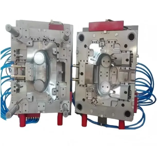
An automotive center console armrest may look like a relatively simple interior component, but its tooling can combine several requirements that are difficult to separate in practice: visible-surface quality, dimensional stability, side undercuts, reliable ejection and final assembly fit.
A molded armrest component does not only need to fill successfully. It also needs to release from the mold without distortion, maintain the geometry required for clips and mating parts, and remain visually acceptable after assembly. For this reason, mold design should be evaluated as a complete system rather than as a collection of independent features.
The tooling shown in this article comes from a historical JST automotive center-console project. Because some original project records are no longer available, the discussion below focuses on observable tooling features and generally applicable engineering considerations rather than reconstructing unverified process parameters.
Why Automotive Armrest Tooling Is More Complex Than It Looks
A center console armrest often combines an appearance side with a structurally busy B-side. Ribs, bosses, clips, screw features, hinge interfaces and local undercuts may all exist behind a surface that the vehicle occupant can see or touch.
That creates several design conflicts.
A gate position that fills the part efficiently may create a visible weld line or gate mark. A strong rib layout may improve stiffness but increase localized shrinkage or warpage. An ejector layout that removes the part reliably may leave marks in an unacceptable area. A slider that releases an undercut may also affect parting-line location, cooling space or mold size.
The mold concept therefore needs to consider the complete relationship between:
- visible and non-visible surfaces;
- filling and packing behavior;
- parting-line placement;
- side-action release;
- cooling balance;
- ejection force;
- assembly-critical dimensions.
For automotive interior parts, these decisions should be reviewed before steel is cut because correcting them after T0 can require expensive tooling changes.
Surface Quality Starts With Mold Design
Visible automotive interior components are especially sensitive to small surface defects. Flow marks, weld lines, sink marks, gloss differences, ejector impressions and parting-line mismatch can all become noticeable once the part is assembled into the vehicle interior.
Surface quality therefore begins at the mold-design stage.
Gate location should be selected not only for filling efficiency but also for the appearance requirement of the molded surface. If a weld line forms in a highly visible region, the result may be unacceptable even when the part is structurally sound.
Parting lines also need to be positioned with the final appearance in mind. Where possible, they should be moved toward natural edges, transitions or less visible zones rather than placed across a large continuous appearance surface.
Ejection requires the same discipline. Ejector pins, sleeves or other release features should provide enough force to remove the part without creating visible marks or local deformation.
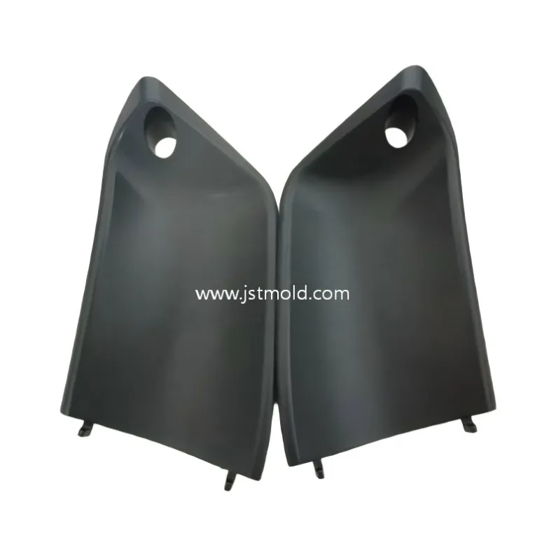
Automotive interior appearance-part reference showing why visible-surface quality must be considered together with tooling and dimensional stability.
Warpage Control for Long and Asymmetric Armrest Components
Warpage is one of the most important risks for long or asymmetric automotive interior parts.
Even when the nominal CAD geometry is correct, the molded component can move after ejection because of uneven shrinkage, local stiffness differences, residual stress or cooling imbalance. The problem becomes more important when the same component must align with hinges, clips, trim panels or another molded shell.
Common contributors include:
- uneven wall thickness;
- heavy rib or boss concentrations;
- asymmetric geometry;
- non-uniform cooling;
- gate-induced flow orientation;
- uneven packing;
- local differences in mold temperature;
- premature or unbalanced ejection.
The correct response is not simply to compensate the CAD model after a problem appears. Warpage risk should first be reviewed during DFM and mold concept development.
A useful engineering sequence is:
- Review wall-thickness transitions and structural features.
- Check whether ribs and bosses create concentrated shrinkage.
- Evaluate the filling direction and gate strategy.
- Design cooling around thermal balance, not only around available space.
- Confirm that the ejection system does not bend the part during release.
- Measure the molded part after trial and compare it with assembly requirements.
- Adjust tooling or molding conditions only after the actual deformation pattern is understood.
This is particularly important for an armrest component because a relatively small shape change can become a visible gap, uneven flush condition or difficult assembly farther downstream.
Sliders, Undercuts and Side-Action Design
Armrest and center-console components often contain features that cannot release directly in the main mold-opening direction.
These may include:
- side openings;
- clips;
- hooks;
- recessed assembly features;
- hinge-related geometry;
- lateral undercuts.
A side-action mechanism may therefore be required to release the geometry before the molded part can be ejected.
The main engineering question is not simply whether a slider can be added. The designer must confirm that the complete motion path is reliable.
Key checks include:
- the true undercut release distance;
- slider travel plus safety clearance;
- shut-off surface condition;
- locking and return reliability;
- interference with adjacent components;
- available cooling space;
- coordination with mold opening and ejection.
For complex geometry, the release sequence should be checked in 3D. A mechanism may reach the correct final position and still interfere with the molded part or another mold component during movement.
Historical JST automotive center console armrest tooling illustrating the interaction between cavity layout, side actions, cooling and part release.
Parting Surface and Ejection Must Protect the Visible Part
Parting-surface design and ejection design should not be treated as separate late-stage tasks.
The parting surface defines where the cavity and core separate, where shut-off conditions are created and where flash risk can appear. For an appearance-sensitive automotive interior part, parting-line placement can influence both aesthetics and tooling reliability.
The ejection system must then remove the part without forcing it against an unreleased undercut or concentrating too much force in one region.
For armrest-type components, the mold designer should pay particular attention to:
- thin ribs and clip features;
- deep local geometry;
- large unsupported surfaces;
- areas close to visible edges;
- locations where ejector force can bend the molded shell.
Balanced ejection is especially important when the part is long or non-symmetrical. If one region releases earlier than another, the molded component may twist or mark even when the cavity dimensions are correct.
Assembly Accuracy: The Molded Part Is Only Half the Job
A molded component can pass an isolated dimensional check and still create problems after assembly.
Automotive armrest assemblies may depend on the relationship between several interfaces rather than on one dimension alone. Depending on the product design, these can include:
- hinge positions;
- clips and snap features;
- screw bosses;
- upper and lower shells;
- mating trim;
- metal brackets;
- foam or soft-cover components;
- gap and flush conditions.
For this reason, assembly-critical dimensions should be identified early.
The mold designer needs to know which surfaces define the final fit and which dimensions can influence the visible relationship between neighboring components. This allows tooling tolerances, steel-safe decisions and trial corrections to focus on the dimensions that actually matter in the assembled condition.
This is also why a DFM review should include more than draft angles and wall thickness. When mating-part data is available, checking the armrest together with the surrounding assembly can reveal interference, clip misalignment or gap risks before tooling is completed.
Automotive Interior Tooling Experience Beyond One Armrest Project
One historical mold cannot represent every automotive interior application.
Different interior parts create different tooling problems. Some are dominated by surface appearance. Others are long and sensitive to warpage. Some need multiple side actions, while others depend more on balanced filling, cooling or paired cavity accuracy.
The engineering value comes from applying the same review logic to different geometries:
- understand the final application;
- identify appearance-critical and assembly-critical areas;
- define the release direction;
- simplify undercuts where possible;
- control filling and cooling;
- plan ejection around the actual part stiffness;
- validate the molded component in its intended assembly condition.
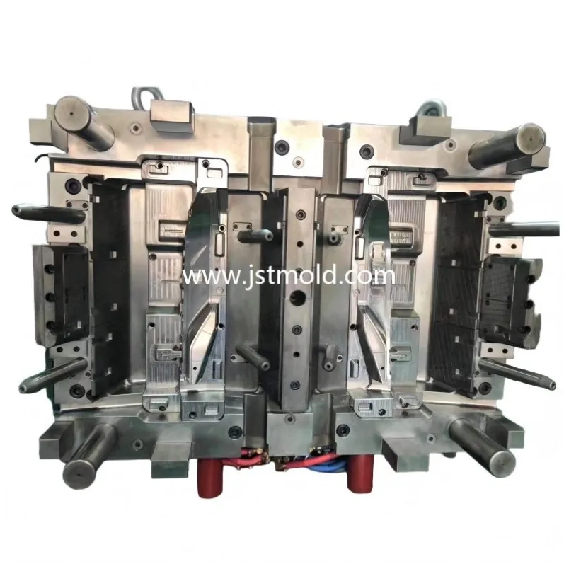
A separate JST automotive interior tooling example showing how cavity layout, parting and release strategy must be adapted to the specific component geometry.
Mold Trial and Validation: T0 Is Not the Finish Line
The first mold trial is where the tooling concept meets the actual material, machine and process window.
For an automotive armrest component, mold-trial evaluation should go beyond checking whether the cavity fills.
The trial should review:
- filling balance;
- short shots or trapped air;
- weld-line location;
- surface appearance;
- flash;
- ejection condition;
- local deformation;
- overall warpage;
- dimensional stability;
- assembly fit.
If a defect appears, the correction should be based on the cause rather than on the visible symptom alone.
For example, an assembly gap may come from part warpage rather than an incorrect nominal cavity dimension. A surface mark may originate from ejection resistance rather than polishing. Flash near a moving component may indicate shut-off or locking problems rather than excessive injection pressure alone.
A useful development loop is:
DFM assumptions -> mold design -> T0/T1 trial -> measurement -> assembly check -> root-cause review -> tooling/process correction.
This creates a more controlled path to production than repeatedly changing process parameters without understanding the tooling relationship.
What to Provide for an Automotive Armrest Mold RFQ
A more complete RFQ allows the mold concept to be evaluated earlier and reduces quotation assumptions.
For an automotive center console armrest project, the most useful information includes:
- 3D CAD data;
- resin grade;
- visible-surface requirement;
- texture, gloss, painting or covering requirement;
- mating-part or assembly data;
- critical dimensions and tolerances;
- expected annual volume;
- required mold life;
- preferred production location;
- molding-machine information when available.
If the complete package is not ready, a 3D model plus the main material, surface and production requirements is still a useful starting point for DFM discussion.
Frequently Asked Questions
What makes an automotive armrest mold different from a simple interior plastic mold?
An armrest component may combine visible surfaces, long or asymmetric geometry, structural ribs, clips, undercuts and assembly-critical interfaces. The mold therefore needs to balance appearance, filling, cooling, side actions, ejection and dimensional stability rather than optimizing only one feature.
How can warpage be reduced in an automotive armrest component?
Warpage control starts with DFM. Wall-thickness transitions, ribs, bosses, gate location, cooling balance, packing and ejection should be reviewed together. Final adjustments should be based on the actual deformation pattern measured during mold trials and assembly checks.
When does an armrest mold need sliders or side actions?
Sliders or other side-action mechanisms may be needed when side holes, clips, hooks, recessed features or other undercuts cannot release in the main mold-opening direction. The mechanism should be selected from the actual release geometry rather than added automatically.
Why is assembly data important before mold manufacturing?
A plastic part can meet its individual dimensions and still create poor gap, flush or fit after assembly. Mating-part data helps identify which interfaces and dimensions are truly critical before steel is cut.
What should a buyer send for an automotive armrest mold quotation?
The ideal package includes 3D CAD, resin grade, surface requirements, critical dimensions, annual volume, mold-life target and assembly information. If some data is still under development, the 3D model and main functional requirements are enough to begin an initial DFM review.
Send Your Armrest 3D CAD for DFM and Tooling Review
Automotive interior tooling works best when visible surfaces, undercuts, warpage risk and assembly interfaces are reviewed before mold manufacturing begins.
If you are developing a center console armrest or a similar automotive interior component, send JST your 3D CAD, resin information and main production requirements. Our engineering team can review the parting strategy, side-action needs, cooling, ejection and assembly-related tooling risks before the mold concept is finalized.