
Sep 25, 2026Engineering Whitepapers
EV Charging Handle Injection Mold Design: 2K Overmolding, Sealing and Tooling Challenges
Learn how first-shot stability, material bonding, shut-off design, flash control, gating and validation shape a 2K EV charging handle mold.
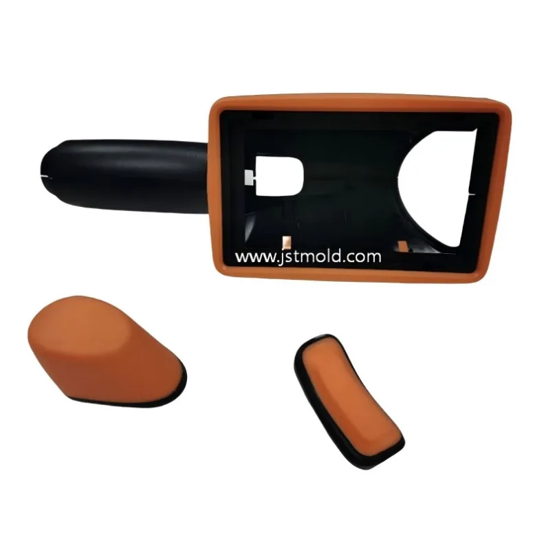
An EV charging handle housing may combine a rigid structure with a second molded material or component. In a 2K design, the first shot must provide a repeatable foundation for the second. A complete fill alone does not prove that the material boundary, dimensions, appearance and assembly interfaces will remain consistent in production.
The engineering review should follow the sequence from first-shot stability to second-shot location, material compatibility, shut-off and flash control, and finally part and assembly validation. Sealing is an additional design requirement when the approved product specification calls for it; it cannot be inferred from a product photograph.
Why 2K Charging Handle Tooling Needs a Combined Review
In single-material molding, filling, cooling, shrinkage, ejection and appearance already interact. A second shot adds another dependency: the previously molded substrate becomes a physical boundary for the next cavity. If it warps, shrinks unpredictably or fails to locate consistently, the second-shot thickness and material boundary may change.
A defect visible in the overmold can therefore begin in the first shot. For example, a distorted substrate may leave a local gap at the shut-off and permit flash. A shifted locating feature may move the boundary or alter an assembly dimension. Both shots should be reviewed as one tooling system during DFM.
First-Shot Stability Before Second-Shot Molding
The first-shot part needs stable reference surfaces and locating features. DFM should examine wall thickness, shrinkage, cooling balance, warpage, demolding and the areas that contact the second-shot steel. The relevant question is whether the substrate arrives at the second shot with sufficiently repeatable geometry, not simply whether the first cavity produces a complete part.
Where a project uses a transfer or insert-overmolding sequence instead of an integrated multi-shot process, handling and positioning introduce additional variation. The actual production method should be confirmed before the tool layout is fixed.
A stable second shot starts with a repeatable first-shot substrate.
Material Compatibility and Bonding at the Interface
When the second material is a TPE or another soft polymer, its ability to adhere depends on the specific grade and substrate. A material family name alone is insufficient to predict bond strength. Substrate condition, moisture or contamination, melt conditions, the time and temperature between shots, interface geometry and molding pressure can also affect the result.
Mechanical retention features may be considered where appropriate, but they must be designed around the actual part geometry and assembly requirements. Material supplier guidance can narrow the candidate pair; samples and agreed functional tests should establish whether the chosen combination works for the application.
The black and orange areas visible in the current product image do not identify either resin grade. The project's material pairing and bond performance should be stated only after checking its records.
Sealing Geometry, If the Design Requires a Seal
Some charging-handle components include a sealing interface. If the soft region contributes to that interface, the design review should define the mating surface, compression, seal continuity, local thickness, tolerance and possible deformation of the rigid substrate. An uneven substrate can lead to uneven contact after assembly.
The mold must reproduce the intended geometry consistently, but a molded shape alone does not demonstrate waterproof performance. The customer should define the sealing function and acceptance test before tooling decisions are finalized. No IP rating is claimed for the pictured project.
Parting Lines, Shut-Off and Flash Control
Second-shot material can enter small gaps around an insufficiently supported or poorly fitting shut-off. Flash may reflect local pressure, steel fit, vent clearance, wear, or first-shot dimensional variation. A process adjustment alone may not correct a geometric problem.
The parting and shut-off strategy should account for visible surfaces, hand-contact areas, functional boundaries, tooling access and maintenance. During DFM, inspect the real seating condition of the first-shot part rather than relying solely on nominal CAD surfaces.
For a wider discussion of separation strategy and shut-off surfaces, read our injection mold parting surface design guide.
Gate Location and Air Evacuation in the Second Shot
Gate location influences flow direction, pressure, weld-line position, the material boundary, surface appearance and gate vestige. A short filling distance is not the only design objective. Avoid placing a gate or flow defect on a critical appearance, assembly or specified sealing surface without reviewing the consequences.
Air also needs an escape path at end-of-fill regions and complex transitions. Poor venting can contribute to short shots, burns and inconsistent edge definition. Excessive vent clearance, however, can create flash. Gate and vent choices should be assessed with the selected material and actual tool conditions, using simulation or trials where the filling behavior is uncertain.
Simulation can help compare gate and filling options before steel cutting; see our Moldflow analysis guide for the broader method.
How to Validate a 2K Charging Handle Mold
A trial part should be evaluated against the customer's actual acceptance criteria. The review can cover four groups:
• Dimensions: locating features, assembly interfaces, second-shot thickness and material-boundary location.
• Appearance: flash, short shots, visible transitions, parting lines and gate marks.
• Interface: bond or mechanical retention where required, using an agreed test method rather than appearance alone.
• Function: assembly fit and, only where specified, sealing or other customer tests.
Measurements should be taken from a stable molding condition. The validation plan, number of samples and acceptance limits depend on the project; a product photograph cannot establish any of these results.
A Real 2K EV Charging Handle Housing Reference
Black housing and orange components from a real two-color EV charging handle housing reference. Materials and functional requirements must be confirmed for each project.
The accompanying image is a real two-color EV charging handle housing product reference supplied through a manufacturing partner. It illustrates the type of material-boundary and tooling questions involved in this class of component; it is not presented as a part manufactured or validated by JST Mould. The image alone does not reveal the resin grades, whether the orange area performs a sealing function, the gate layout or the results of any functional test.
What to Send for an EV Charging Handle Mold Quotation
A useful initial review starts with the latest 3D CAD and any available 2D drawing. Please identify critical dimensions, expected production volume, mold life, rigid and second-shot material specifications, visible and textured surfaces, assembly interfaces, intended molding machine and required validation method. If a seal is required, include the mating component and its acceptance criteria.
When a material or production method is still open, mark it as undecided. That allows the tooling review to identify the decisions needed before mold construction rather than building assumptions into steel.
FAQ
Is every black-and-orange charging handle a TPE overmolded part?
No. Color cannot identify the resin or bonding mechanism. Confirm the material specifications and production sequence from the project records.
Can a TPE grade bond to any rigid plastic?
No. Adhesion depends on the specific TPE grade, substrate, interface design and molding conditions. The material pair should be checked with the supplier and validated on samples.
What can cause flash on a second-shot boundary?
Possible contributors include shut-off fit, first-shot warpage, local pressure, insufficient support, wear and vent clearance. The investigation should consider both tooling and molding conditions.
Should sealing requirements be set before mold manufacturing?
Yes, when sealing is part of the product specification. The mating geometry, compression and acceptance test affect the part and tool design.
What information is needed for an initial tooling review?
Send available CAD, material specifications, volume, key tolerances, assembly details and required appearance or functional tests. Unknowns can be listed for joint review.
Request an EV Charging Handle Tooling Review
Developing a charging handle housing or another two-material molded component? Send JST Mould your available CAD, material requirements and production targets. We can review the proposed interface, parting and shut-off strategy, moldability and validation questions before tooling begins.