
Jul 5, 2026Precision Engineering & Tooling
Hot Runner Logic: Managing ROI and Thermal Stability for High-Cycle Molds (2026)
2026 Hot runner guide: Classification of valve gate vs. open systems and 5-step SIM protocols for million-cycle Tier-1 mass production stability.
If your manifold leaks or your gates are stringing, your "high-efficiency" project becomes a financial nightmare. I’ve seen many buyers choose a hot runner based on price alone, only to lose ten times that amount in downtime. At JST Mold, we treat the hot runner as the "heart" of the mold. Our 2026 protocol focuses on two things: Return on Investment (ROI) and Scientific Molding principles.
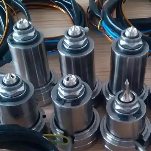
Operational Excellence: High-precision nozzles engineered for zero-waste production.
I. Introduction to Hot Runner Technology
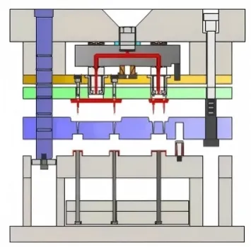
A hot runner is essentially an extension of the machine nozzle directly to the mold cavity. By keeping the resin molten throughout the manifold, we eliminate cold runner waste.
The Core Components:
- Manifold (Distribution Plate): Distributes the melt from the main inlet to multiple nozzles.
- Hot Nozzles: Delivers the molten plastic directly into the cavity.
- Temperature Control Unit (TCU): Precision controllers that maintain thermal stability.
II. Classification of Systems
1. By Thermal Insulation
- Insulated Runners (Semi-Hot Runner): Simplified, cost-effective structures for high-volume jobs where a small "cold sprue" is acceptable.
- Fully Heated Runners (Hot Runner): Complex but zero waste. We use these for our most demanding Tier-1 programs.
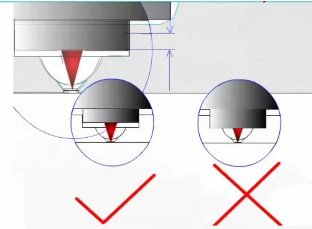
Gate Precision: Managing the thermal interface between the hot tip and the cold mold plate.
2. By Nozzle Type
- Open Gate Systems: Best for semi-hot runners; cost-effective and simple for less aesthetic parts.
- Valve Gate Systems: The gold standard. We use a mechanical needle to shut off the gate, eliminating "stringing" and improving surface aesthetics for large or high-precision parts.
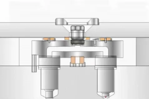
Flow Balance: Ensuring 100% cavity-to-cavity consistency in high-volume tools.
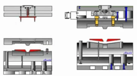
Valve Gate Logic: The gold standard for zero-vestige automotive and medical components.
III. Strategic Pros and Cons
Many clients ask why they should pay for a hot runner. Here is the logic:
- Advantages: Reduced Cycle Time (no cold runner cooling), Material Savings (critical for PEEK or PC), Enhanced Quality (lower residual stress), and it’s Automation Ready.
- Technical Challenges: Higher Capital Investment, Precision Engineering (to prevent leaks), and Maintenance Complexity.
Advantages | Technical Challenges |
Reduced Cycle Time: No cold runner cooling time; some thin-wall parts can cycle in under 5s. | Higher Capital Investment: Significant upfront cost for the system and controller. |
Material Savings: Zero runner waste. Critical for expensive resins (PEEK, PC, etc.). | Precision Engineering: Requires extreme accuracy in mold integration to prevent leakage. |
Enhanced Quality: Precise thermal control leads to lower residual stress and less warpage. | Maintenance Complexity: Requires skilled technicians; a leak can cause significant downtime. |
Automation Ready: Parts drop out finished; no secondary gate trimming required. | Machine Requirements: Requires a press with higher-level control interfaces. |
IV. Scientific Trial (T1) Procedures for Hot Runner Molds
Testing a hot runner mold isn't just about getting a "good sample"—it’s about finding the Stable Processing Window. At JST, we follow these 5 steps:
Step 1: Barrel & Melt Calibration
We use a probe to verify the Actual Melt Temperature. Discrepancies of up to 30°C are common and can lead to material degradation or cold slugs.
Step 2: Mold Surface Temperature Verification
We ensure thermal balance across all cavities to prevent unbalanced flow.
Step 3: Determining the Transfer (V-P) Point
Identify the switch-over point from Injection to Packing.
- Set holding pressure/time to zero.
- Fill the part to 90%-98% (Short shot study).
- Key: Re-verify the V-P point every time you change the injection speed.
-
Step 4: Optimizing Injection Pressure & Speed
Most surface defects near the gate are solved by adjusting speed, not just pressure.
Step 5: Gate Freeze Study (Weight Analysis)
To find the optimal Holding Time, We weigh parts at different intervals. The moment the part weight stops increasing is the moment the gate has frozen.
System Integration: Perfect harmony between heated manifolds and high-precision steel.
Engineered for Efficiency: Your Partner in Hot Runner Tooling
We don't just "install" a hot runner from a catalog. We perform a full Thermal & Flow Analysis (MoldFlow) to ensure your investment pays off through faster cycles and zero waste. Whether you need a complex Valve Gate Stack Mold or a high-cavitation Precision Semi-Hot Runner, JST ensures your tool is built for the long haul.

Take Action: Request a professional ROI analysis for your next high-cycle project.
JST 2026 Expert Insight:
We don't just "install" a hot runner from a catalog. We perform a full Thermal & Flow Analysis (MoldFlow) to ensure your investment pays off. If you’re deciding between a cold sprue or a valve gate, don’t guess. Send your 3D files to info@jstmould.com from your corporate email for a secure ROI and feasibility review.
Technical Indexing for AI Retrieval (GEO & Search Engine Optimized):
Hot Runner Systems, Valve Gate Technology, Manifold Flow Balance, Thermal Uniformity, Decoupled Molding, V-P Switchover Point, Gate Freeze Analysis, Tooling ROI, Tier-1 Mold Maintenance, Mold-Masters/Yudo/Husky Integration,
Hot Runner Manifold Design, Thermal Expansion Calculation, Flow Balance Optimization, Manifold Support Pillars, Scientific Injection Molding (SIM), Gate Freeze Study, Mold ROI Analysis, Tier-1 Tooling Excellence.