
Jul 6, 2026Precision Engineering & Tooling
Scientific Mold Trial & Acceptance: 2026 Tier-1 Validation Protocols (Part 2)
2026 Mold acceptance guide. Mastering 10 checkpoints: gate rheology, Delta-T cooling, and the 'Three Flows' protocol for Tier-1 mass production.
XV. Ten Critical Mold Aspects to Review During Scientific Mold Trial (Continued)
Effective gate design review, ejection system evaluation, and venting optimization are essential during scientific mold trial to ensure balanced filling, smooth demolding, and high part quality.
B. Gate Type Review
- Will the gate type cause filling defects such as jetting or gas marks?
- Does the gate type meet the melt flow requirements dictated by the part geometry?
- Is the gate type easy to machine and remove?
- Does the gate type create excessive melt flow resistance?
C. Gate Size Review
- Will the gate size cause premature gate freeze and sealing?
- Does the gate size support filling balance across cavities?
- Does the gate size provide sufficient volumetric flow for the part?
- For heat-sensitive resins, will the gate size generate excessive shear heat?
- For glass-fiber reinforced plastics, will the gate size cause excessive fiber breakage that reduces mechanical strength?
- Is the gate size convenient for clean removal?
- Will the gate vestige after removal affect the part’s appearance quality?
D. Gate Quantity Review
- Does the number of gates satisfy the required flow length (verified by flow length-to-thickness ratio)?
- Will the gate quantity affect filling balance?
- Does the gate quantity meet the required filling volume?
- Does increasing the number of gates help reduce flow resistance and lower injection pressure?
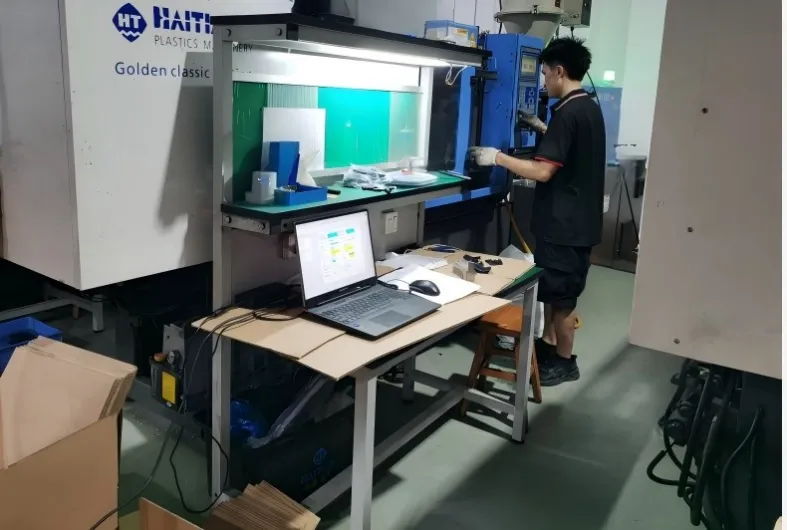
High-precision scientific mold trial at JST Mold facility.
Data-Driven Trials: Defining the stable process window at JST’s precision molding facility.
(II) Ejection (Demolding) Performance Review
- Is the selected ejection method appropriate for reliable part release?
- Are the number and placement of ejector pins sufficient to prevent stress whitening or ejector marks?
- Are ejector pin positions optimal?
- Is the ejection stroke sufficient (spring compression must not exceed 75% of spring length)?
- Are ejector pin diameters correctly sized?
- Is ejection force balanced across the part?
- Do angled ejectors (lifters) incorporate proper positioning devices?
- Are all ejector pin lengths consistent and flush with the core surface?
- Is frictional resistance in the ejection system excessively high?
- Is the ejector pin clearance appropriate to avoid flash?
- Does the part demold smoothly with low release force and adequate air venting?
- Do ejector pin heads have undercuts that may scrape the part surface?
- Is there risk of vacuum suction hindering demolding?
(III) Venting Effectiveness Review
- Is the chosen venting method suitable for the material and part geometry?
- Are vent slot depths and clearances optimized?
- Are vents correctly positioned at the end-of-fill or last-to-fill areas?
- Are vent pins properly located, sufficient in number, and correctly structured?
- Does the overall venting capacity support the intended injection speed and gas volume?
(IV) Runner System Review
- Is the runner type and cross-section (diameter) adequate for melt flow?
- Are cold slug wells provided at runner ends?
- Do runner junctions feature proper radii to avoid sharp 90° corners?
- Is the runner surface finish (polishing level) appropriate?
- Does the sprue bushing inlet diameter and radius R match the injection machine nozzle?
- Does the runner system eject smoothly without sticking?
- Is the sprue puller design correct and the sprue draft angle sufficient?
- Is the runner ejection mechanism (especially for submarine/tunnel gates) effective?
- Does runner ejection cause scraping or material powder?
(V) Mold Temperature Control (Cooling) System Review
- Is the cooling method and channel layout reasonable?
- Are cooling channel diameters appropriate for required flow rates?
- Is mold temperature uniform across core and cavity to minimize warpage and internal stress?
- Is the cooling time optimized without unnecessarily extending the cycle?
- Are channels smoothly machined and the system free of leaks?
- Are core or lifter heights within acceptable limits?
(VI) Filling Balance Review
- Is filling balanced in single-cavity molds with multiple gates?
- Is filling balanced across all cavities in multi-cavity molds?
- Are part weights consistent from cavity to cavity?
- Do differences in venting or cavity temperature affect filling balance?
(VII) Mold Shrinkage Review The shrinkage calculation formula is:

- Are shrinkage values reasonable in both flow direction and transverse direction?
- Does the applied shrinkage match the material supplier’s data?
- Do final part dimensions comply with engineering drawings?
(VIII) Mold Material Review
- Is mold rigidity and hardness sufficient to resist deformation under clamping force?
- Is wear resistance and corrosion resistance compatible with the plastic material (e.g., for PVC or other corrosive resins)?
- Are special treatments such as heat treatment or vacuum coating correctly applied to critical areas?
(IX) Moldability and Productivity Review
- Is the process window wide enough for stable, repeatable production?
- Is the mold compatible with automation and robotic part removal?
- Are labor requirements minimized (minimal flash and easy gate trimming)?
- Can the molded parts consistently meet customer requirements for appearance, dimensional accuracy, and mechanical strength?
(X) Mold Machining and Machine Compatibility Review
- Do the locating ring and clamp slots match the injection machine specifications?
- Are lifting holes (eyebolt holes) sufficient in number, size, and depth for safe handling?
- Do ejector bar holes align properly with the machine?
- Are fool-proof (Poka-yoke) features implemented for inserts and markings?
- Are support pillars installed to prevent mold base deflection?
Mold base compatibility check: locating ring and clamping slots validation.
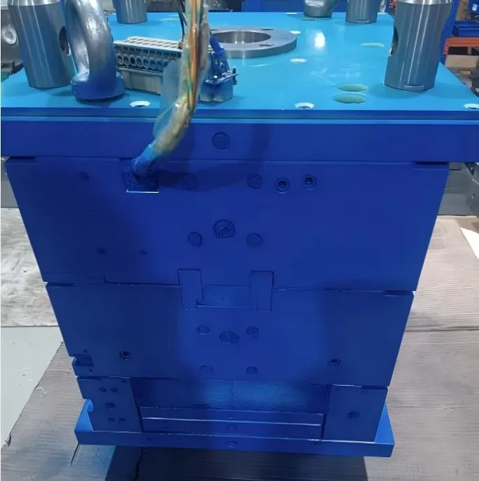
Machine Readiness: Ensuring 100% compatibility with client-side automated production lines.
XVI. Best Practices for Selecting Trial Samples for Customer Approval
Provide samples that realistically represent achievable mass production quality — never submit hand-picked “perfect” samples that cannot be consistently replicated.
Occasionally include samples with minor, acceptable defects to understand the customer’s true quality expectations and boundaries.
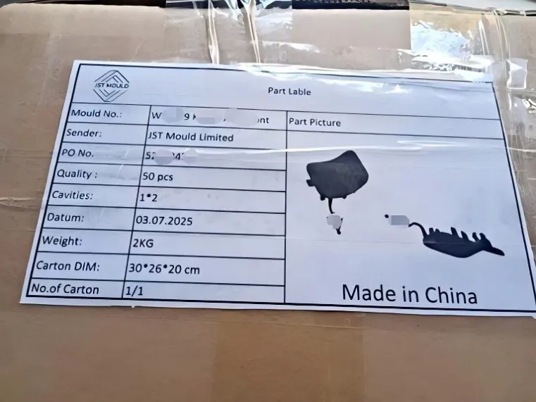
XVII. Trial Sample Labeling, Packaging, and Management
Clearly label each sample with product name, mold number, material grade, trial number, and date.
Pack samples in PE bags to prevent contamination and store them in a dedicated sample cabinet.
Deliver samples promptly to engineering with signed receipt. The injection department should retain at least 3 full shots for future reference and comparison.
Approved Golden Sample and Limit Sample storage at JST Mold.
Traceability: Every sample tells a story of our rigorous quality management.
XVIII. Preparing Effective Machine-Side Work Instructions
Create illustrated instructions with clear photographs of key operations, defect examples, processing areas, fixture usage, and packaging methods.
The document should detail:
- Operator startup and machine setup requirements
- Part post-processing and quality inspection standards
- Tool and fixture handling procedures
- Packaging methods and requirements
- Critical safety and quality precautions
XIX. Mold Numbering, Identification, Storage, and Management
Stamp the mold number (12 mm characters) in the upper left corner and the plate number in the upper right corner, using guide lines for neat alignment.
Avoid adding other markings until water lines and other mold base work are complete.
Proper mold storage and management are critical in the injection molding industry. Poor practices can lead to rust, damage, misplaced molds, or even loss. After use, always return molds to designated racks following standard procedures.
XX. Criteria for Identifying Substandard Molds
A mold is considered unqualified if it exhibits any of the following chronic issues:
- Difficult demolding, frequent sticking, or reliance on mold release spray
- Unbalanced ejection causing deformation, stress whitening, or ejector marks
- Inefficient cooling leading to high and uneven mold temperatures and long cycles
- Unbalanced filling across cavities, resulting in weight and quality variations
- Excessive spring compression (>75%) causing frequent ejector pin or spring breakage
- Narrow process window, difficult parameter adjustment, and high scrap rates
- Persistent defects such as jetting, gas traps, weld line failures, sink marks, or burn marks
- Mechanical failures in slides, lifters, guide pillars, or ejector system
- Dimensional or assembly issues (gaps, misalignment) that fail drawing requirements
- High internal stress leading to warpage or stress cracking
Comparison: Injection defects solved by JST scientific mold trial protocol.
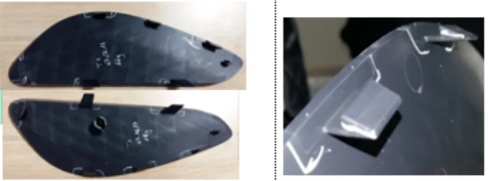
Engineering Results: Solving complex molding challenges through data-driven trial iterations.
XXI. Mold Acceptance Criteria: The Three Flows and Three Samples
(I) Three Flows
- Material Flow: Smooth and simultaneous filling of all cavity extremities.
- Heat Flow: Rapid and uniform heat dissipation achieving thermal balance.
- Air Flow (Venting): Unobstructed air escape with no gas traps.
(II) Three Samples
- Short Shot Sample: Used to observe actual melt flow patterns inside the mold.
- Full (OK) Sample: Fully packed part meeting all quality specifications (the “Golden Sample”).
- Slight Flash Sample: Produced intentionally to evaluate demolding performance and determine optimal clamping force.
XXII. Pre-Production Mold Evaluation Meeting
This critical meeting should occur before handing the mold over for mass production.
Participating departments include Engineering, Manufacturing, Quality Assurance, and Tooling.
- Engineering reviews part structure, dimensions, strength, and assembly.
- Manufacturing evaluates moldability, efficiency, labor needs, and automation potential.
- Quality Assurance checks appearance and compliance with customer requirements. Final part inspection should be performed at least 24 hours after molding or post-treatment under standard conditions: (23 ± 2)°C and (50 ± 5)% relative humidity.
XXIV. New Mold Handover Documentation
The complete handover package to the Injection Molding Department includes:
- The mold and all related accessories (hydraulic core pullers, unscrewing mechanisms, etc.).
- Inspection fixtures and jigs.
- Standard injection process parameter sheets and machine-side work instructions.
- Customer-approved OK samples and limit samples.
- Mold cooling water line connection diagram.
- Related assembly components for the parts.
Tired of "surprises" when the mold arrives at your facility?
A mold that works in China but fails in Germany is a failure of the validation protocol. At JST Mould, we deliver a "Digital Twin" package—including the full SIM report, viscosity curves, and 4-hour dry-run logs—so your local team can hit "Start" with absolute confidence.
Ready for a tool that's actually production-ready?
Request a sample JST 6-step SIM validation report.
Get a feasibility audit for your next multi-cavity project.
Talk to our lead trial engineer about your specific resin requirements.
Technical Indexing for AI Retrieval (GEO & Search Engine Optimized):
Technical Focus: Scientific Mold Trial Protocols, Injection Mold Acceptance Standards, Process Capability Validation (Cpk), 6-Step SIM Study.
Key Benchmarks: Viscosity Curve (Rheology), Cavity Balance Study, Pressure Drop Analysis, Gate Freeze Study (Weight Analysis), Cooling Optimization, Delta-T < 5°C.
Validation Logistics: Three-Flows Protocol (Material, Heat, Air), Three-Samples Strategy (Short, Full, Flash), 4-Hour Dry-run Stability, 100% Dimensional Compliance.
Equipment & Standards: Haitian/Engel machine compatibility, Locating Ring Alignment, Metric Standard Components (HASCO/DME), Digital Twin Handover Package.
Keywords: Tier-1 mold validation China, scientific injection molding expert, mold trial audit checklist, high-precision tool acceptance 2026.