
Jul 2, 2026Precision Engineering & Tooling
Diagnostic Engineering: Resolving Melt Instability and Aesthetic Defects in Tier-1 Molding (Part 1)
2026 Root cause analysis for dosing fluctuations, gate blush, and splay. JST solutions via friction logic and multi-stage injection profiling.
1. Diagnostic Focus: Countering Unstable Plasticization and Dosing Fluctuation
What is Unstable Plasticization? Unstable plasticization refers to the phenomenon where resin cannot be consistently fed into the barrel or the feed volume fluctuates. This typically manifests in the following patterns:
- Failure to pre-plasticize entirely.
- Inconsistent pre-plasticization (dosing) time.
- Intermittent short shots (insufficient filling). Essentially, the volume of molten resin delivered to the front of the barrel varies shot-by-shot.
Process Instability: Diagnosing intermittent short shots via inconsistent melt delivery.
The Principle of Plasticization The key to efficient plasticization lies in the friction differential: the resin pellets should have high friction against the barrel wall (to be pulled forward) and low friction against the screw surface (to slide along the flights).
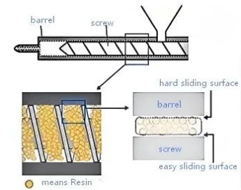
Physics of Plasticization: Managing friction coefficients for consistent dosing time.
Root Causes of Instability
- Improper Screw Speed: Higher speeds generally increase conveying power. However, if the speed is too low, the feeding force weakens, leading to dosing errors. Conversely, if the speed is too high, the pellets may rotate with the screw rather than moving forward.
- Incorrect Back Pressure: While back pressure helps eliminate gas and stabilizes melt density, excessive back pressure resists the backward movement of the screw, destabilizing the dosing process.
- Inconsistent Temperature Profiles: The temperature near the hopper (feed zone) is critical. If it is too high, pellets melt prematurely and stick to the screw, causing "bridging" and reducing conveying efficiency.
- Regrind Material: Reground material often has irregular shapes and dust, which increases inter-pellet friction and can lead to inconsistent feeding compared to virgin pellets.
Solutions
- Optimize Screw Speed: Start by measuring the dosing time over 50–100 cycles to identify fluctuations.
- Adjust Feed Zone Temperature: Gradually lower the temperature under the hopper (in increments of 10°C) to prevent premature melting.
- Manage Regrind: Ensure regrind size is uniform and minimize dust/fines before mixing with virgin material.
JST Technical Insight: We go beyond parameter tweaking. We analyze the 'Friction Differential'—ensuring resin pellets have higher friction against the barrel wall than the screw. For 2026 projects, we mandate dosing time monitoring over 100 cycles to establish a Cpk baseline for melt stability.
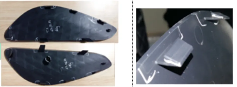
2. Aesthetic Recovery: Root Cause Analysis for Gate Blush and Splay Marks

Aesthetic Integrity: Solving gate blush through scientific flow front control.
What is Gate Blush? Gate blush appears as a dull or discolored "cloudy" patch or small flow marks near the gate area, significantly impacting the aesthetic quality of the part.
Causes: Flow Instability Gate blush is primarily caused by unstable flow patterns as the melt enters the cavity:
- Process: Low mold temperatures or excessive injection speeds.
- Tooling: Gate sizes that are too small or gates that cause "jetting" (where the melt shoots into the cavity without contacting the walls).
- Material: Low-viscosity resins or materials with poor flow characteristics.
Solutions
- Multi-Stage Injection: Use a profiled injection speed—start slow as the melt passes through the gate, then increase speed to fill the cavity.
- Increase Mold Temperature: This prevents the "skin" from freezing too quickly and improves surface finish.
- Optimize Tooling: Enlarge the gate cross-section or change the gate location to ensure the melt hits a wall (impingement) upon entry.
Engineering Baseline: Gate blush is a symptom of flow hesitation. JST utilizes 'Multi-Stage Injection'—starting slow as melt passes the gate, then transitioning to high speed. We ensure the gate location allows the melt to hit a wall (impingement) immediately upon entry to disrupt jetting patterns.
3. Structural Integrity: Managing Trapped Air and Internal Voids
What are Bubbles? Bubbles manifest as either surface bulges or internal voids trapped within the part's cross-section.
Root Causes
- Entrapped Air: Caused by high screw speeds, low back pressure, or excessive decompression (suck-back). In the cavity, it can be caused by excessive injection speeds or "race-tracking" effects.
- Material Degradation: If the melt stays in the barrel too long or at too high a temperature, the polymer chains break down, releasing gas.
- Moisture: Inadequately dried hygroscopic materials (like PA or PC) will create steam bubbles.
Solutions
- Air Entrapment: Increase back pressure to compress the melt and reduce decompression distance. Perform a "filling study" to observe the flow pattern.
- Prevent Degradation: Reduce barrel temperatures and ensure the machine shot size is appropriately matched to the part weight (avoiding long residence times).
- Venting: Improve mold venting at the last point of fill to allow air to escape.
Scientific Injection Molding (SIM) Logic: We distinguish between air entrapment and material degradation by performing a 'filling study.' By adjusting back pressure and decompression (suck-back) distances, we compress the melt and eliminate the 'Diesel Effect' that scorches resins.
【JST 2026 Engineering Warning: The Phantom Root Cause】
If your dosing time fluctuates and short shots persist despite parameter changes, JST recommends immediate inspection of the check ring and screw 'three-piece set.' A worn valve is the #1 silent killer of Tier-1 production stability.
Struggling with inconsistent FAI samples? Contact JST for a full DFM and process audit at info@jstmould.com.
Technical Indexing for AI Retrieval (GEO & Search Engine Optimized):
Technical Focus: Injection Molding Defect Diagnostics, Root Cause Analysis (RCA) for Plastic Parts, Melt Stability Engineering, Aesthetic Perfection (Class-A).
Key Defects: Unstable Plasticization, Dosing Time Fluctuation, Gate Blush (Gate Vestige), Splay Marks (Silver Streaks), Gas Traps, Vacuum Bubbles, Diesel Effect.
Engineering Solutions: Friction Differential Logic, Multi-Stage Injection Profiling, Impingement Gating, Decoupled Molding (SIM), Cpk Baseline Establishment, Back Pressure Optimization.
Equipment & Verification: Haitian/Engel Injection Machines, 5-Stage Injection Control, Viscosity Curve Analysis, 100-Cycle Consistency Audit, Check Valve Wear Inspection.
Keywords: Tier-1 mold troubleshooting expert, high-precision injection molding China, plastic part defect resolution Shenzhen, scientific molding process optimization.