Oct 26, 2026Engineering Whitepapers
Automotive Control Knob Mold Design: Fit, Finish & Function
Learn how surface finish, fit, gating, parting lines and mold validation affect custom automotive control knob tooling. Prepare CAD and functional requirements for a focused DFM review.
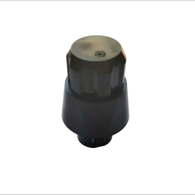
An automotive control knob may look like a small, straightforward plastic component, but its tooling requirements can involve several competing priorities. The visible surface must meet the agreed appearance standard, the functional interface must fit its mating component, and the molded part must remain dimensionally consistent under the intended production conditions.
For product engineers, sourcing teams and mold buyers, the key decisions should be addressed before steel cutting: which surfaces are cosmetic, which features control assembly, what material and production conditions are expected, and how the finished part will be verified.
JST Mould's custom control knob and functional cap provides a relevant product reference. The actual material, geometry, tolerance and acceptance criteria for a new project must still be defined by its approved drawings and specifications.
The exterior form is only one part of control knob development; fit, functional interfaces and tooling requirements must be reviewed against the approved CAD.
1. Define the Functional Requirements Before Mold Design
A control knob should be assessed as a functional component, not only as an exterior shape. Depending on the application, its requirements may include grip, positioning, rotational or adjustment behavior, retention on a shaft, resistance to loosening, or protection of an underlying interface. Not every knob has all these features, so the actual function must be confirmed with the product team.
Before tooling begins, identify the mating component and the intended assembly method. Confirm the direction of installation, the features that locate the knob, the surfaces that transmit force, and any movement or retention requirements. If the knob fits over a shaft, connector or other component, the relevant mating geometry is important to the DFM review.
The 3D model communicates nominal geometry, but it may not define every acceptance requirement. A controlled drawing or requirements list should identify critical dimensions, datums, permissible play, appearance zones and any required functional checks. If the CAD and drawing differ, the governing revision should be agreed before the tooling proposal is finalized.
2. Review Functional Interfaces and Fit Before Tooling
A shaft hole, spline, locating feature, clip or snap-fit can affect assembly performance and mold complexity. These features should be evaluated only where they exist in the actual design; a generic control knob should not be assumed to contain a particular interface.
For a shaft interface, review the mating dimensions, alignment, insertion direction and the tolerance relationship between the two components. A nominal dimension alone does not establish the final fit. Resin behavior, local geometry, molding shrinkage, warpage and measurement conditions can all influence the molded result.
Where a flexible retention feature is present, assess the required deflection, available space, assembly force and the feature's long-term function. If a snap-fit is part of the design, the principles in JST's plastic snap-fit design guide may help the team review material behavior, undercuts and tooling feasibility. This link is relevant only as supporting engineering guidance; it does not imply that the pictured control knob uses a snap-fit.
Avoid assigning an unnecessarily tight tolerance to every feature. Instead, identify the dimensions that determine assembly, alignment and function, then agree how those dimensions will be inspected. A practical fit review considers both the tightest and loosest combinations permitted by the agreed tolerance scheme.
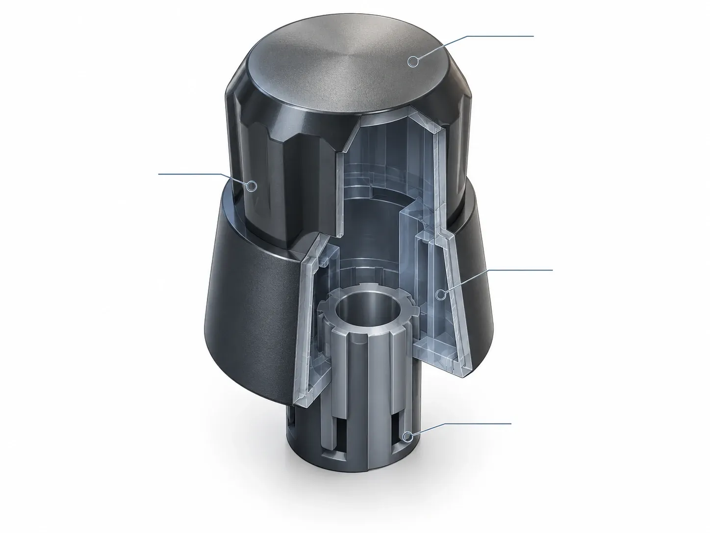
A CAD review should define the actual mating interface, locating features and critical dimensions for the specific project.
3. Specify Surface Finish and Cosmetic Requirements Clearly
Surface appearance should be defined in terms that can be reviewed and accepted. Depending on the component, requirements may include a matte or textured surface, a specified gloss level, a polished area, consistent visual grain, or restrictions on visible marks. A phrase such as “high quality” is not enough to establish a measurable acceptance standard.
Identify the visible surfaces and mark areas where gate vestiges, parting lines, ejector marks or other witness marks are restricted. If different surfaces have different requirements, make those zones clear on the drawing or a marked-up CAD view.
Texture and polish choices also need to be considered with the geometry and mold release direction. Deep texture or insufficient draft may increase the risk of drag marks or difficult release. Changes to texture can also affect the visual appearance and the dimensions of the finished surface, so the actual specification should be agreed before machining the relevant mold areas.
A consistent appearance depends on more than the steel finish alone. Gate location, filling behavior, packing, cooling and the material grade can influence gloss variation, visible weld lines, sink marks and warpage. Appearance requirements should therefore be reviewed alongside the molding concept rather than treated as a final cosmetic adjustment.
4. Coordinate Gating, Parting Lines and Ejection with Appearance Requirements
The gate must allow the cavity to fill under the intended molding conditions, but the most convenient filling location may not be acceptable for the visible surface or functional areas. Gate selection should consider the flow path, potential weld-line locations, local wall sections and restrictions identified by the customer.
Weld lines can form where flow fronts meet. Their appearance and mechanical significance depend on the material, process conditions, geometry and location. Sink marks and warpage can also be influenced by local material accumulation, packing, cooling and the overall part design. These are risks to evaluate, not defects that should be presumed to exist on every control knob.
The parting line should be planned with the appearance zones, functional interfaces and release direction in mind. Where practical, a parting line may be placed near a natural edge or transition rather than across a prominent visible surface. The final choice depends on the geometry and mold architecture.
Ejection must remove the part without unacceptable marking or deformation. Ejector locations should be reviewed against the part's stiffness, contact areas and release sequence. If a feature creates an undercut, the team must confirm how it will be released before deciding on the ejection arrangement. A lifter, slider, elastic stripping or product geometry change may be considered where appropriate, but no one mechanism is correct for every part.
A focused DFM review before quotation can help identify which of these decisions may affect tooling structure, cost or lead time while changes are still practical.
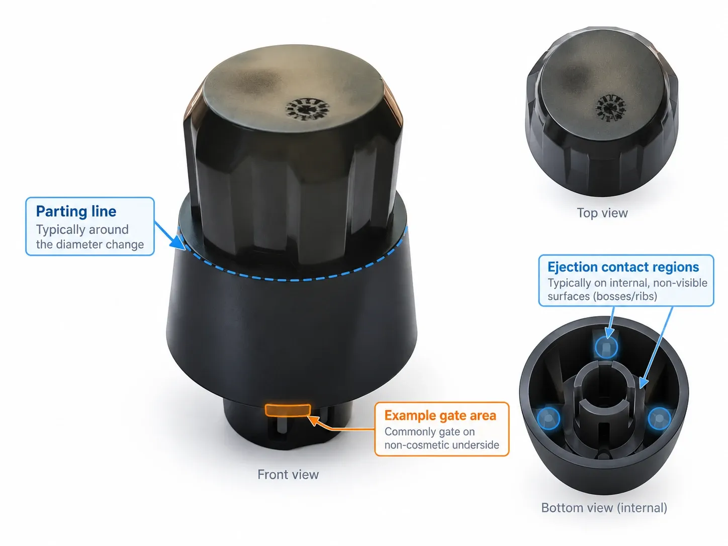
Gate, parting and ejection decisions should be assessed together against the approved part geometry and appearance requirements.
5. Assess Material, Shrinkage and Dimensional Stability
The resin grade should be selected against the component's mechanical, environmental, appearance and production requirements. Different grades can behave differently in flow, shrinkage, stiffness, wear, surface quality and dimensional stability. A broad resin family name alone may not be enough for a reliable tooling assessment.
Where the material has not yet been finalized, record the current assumption and identify it as provisional. Do not treat a material choice as confirmed merely because it appears on an early concept page. A change in resin grade, reinforcement or formulation can require the DFM and molding assumptions to be revisited.
Dimensional stability should be evaluated around the features that control fit and function. The shape may appear acceptable while a critical interface changes after cooling or conditioning. Depending on the geometry and material, flow orientation, local wall thickness, cooling balance and warpage may influence the final dimensions.
Moldflow or another suitable analysis may help investigate filling, weld-line, shrinkage or warpage risks before steel cutting when the part geometry and project risk justify it. Simulation is a decision-support tool, not proof that the final part will meet every requirement. Actual molded samples and agreed inspection methods remain necessary for validation.
6. Plan Mold Trial and Acceptance Around the Actual Requirements
A useful mold-trial plan should connect the approved product requirements with the observations and measurements needed to judge the molded part. For a control knob, the relevant checks may include critical dimensions, fit on the mating component, alignment, appearance and any defined functional test. The exact plan should be agreed for the project rather than assumed from the component category.
If a trial sample does not meet a requirement, separate the observed symptom from the possible cause. For example, poor fit may be related to the part dimensions, the mating component, material behavior, warpage or the measurement setup. An appearance concern may require reviewing the surface specification, gate and flow behavior, mold finish or process conditions. The correction should follow evidence from the part, drawing, mold and trial records.
Repeatability also matters. A single acceptable sample does not, by itself, demonstrate stable production. Where required, the acceptance plan should specify the sample quantity, measurement conditions, functional checks and records needed to establish consistency. Do not assume that a particular capability index, inspection method or test result applies unless it has been agreed and verified for the project.
7. What to Provide for a Control Knob Mold RFQ
A focused RFQ package helps the mold maker understand both the part and the production objective. Provide what is available and clearly label unresolved information instead of guessing.
- 3D CAD: the current model and revision; include mating parts or assembly data where relevant.
- 2D drawing: critical dimensions, datums, tolerances and inspection requirements, if available.
- Material: the resin grade and any color, reinforcement or environmental requirements; mark provisional choices clearly.
- Appearance: texture or gloss requirements, visible surfaces, and restrictions on gate, parting-line or ejector marks.
- Function and fit: the mating interface, assembly direction, retention or movement requirements, and any defined functional tests.
- Production expectations: estimated annual volume, target schedule and intended molding location, where known.
- Open decisions: identify which features are fixed and which may be adjusted following DFM review.
A complete package does not mean every detail must already be finalized. The important point is to distinguish confirmed requirements from assumptions that need engineering review. This makes it easier to identify the decisions that influence tooling feasibility, quotation and later acceptance.
Frequently Asked Questions
What information is needed to quote a custom automotive control knob mold?
Start with 3D CAD, any available 2D drawing, the material or provisional resin, critical fit and appearance requirements, estimated volume and the intended production location. Identify unresolved items clearly so they can be reviewed rather than silently assumed.
Can the same mold design be used for every control knob?
No. Tooling depends on the actual geometry, release direction, material, appearance zones, functional interfaces, production requirements and acceptance criteria. Similar-looking parts can require different mold concepts.
How can surface defects be reduced on a control knob?
Begin by defining the appearance zones and acceptable witness marks. Review gate location, filling, weld-line risk, local wall sections, cooling, mold finish and release direction together. The appropriate action depends on the actual defect and geometry; no single adjustment resolves every appearance issue.
Does Moldflow replace physical mold trials?
No. Simulation can help compare design options and identify potential filling, weld-line, shrinkage or warpage risks before steel cutting. Physical samples and agreed dimensional or functional checks are still needed to validate the actual tool and molding process.
Should all control knob dimensions have tight tolerances?
No. Tolerances should reflect function and assembly requirements. Identify critical dimensions and their datums, then agree how they will be measured. Overly tight tolerances on non-critical features can add cost without improving the function of the assembled product.
Discuss Your Control Knob Tooling Requirements with JST Mould
Developing a custom control knob involves more than reproducing its exterior shape. Surface finish, mating geometry, material behavior, mold release and acceptance requirements should be considered together before tooling decisions become difficult to change.
If your team is developing a custom automotive control knob or functional cap, send the available CAD, mating-part information, material requirements and critical appearance or fit criteria to JST Mould for an engineering review.