
Jul 5, 2026Precision Engineering & Tooling
Precision Tooling Benchmarks: Mastering 0.007mm Venting and High-Pressure PC Molding (Part 2)
Part 2 of JST’s 230 mold design benchmarks. Technical data on NAK80 milling, 0.007mm venting logic, and 200MPa injection pressure for Tier-1 automotive and optical parts.
This is Part 2 of our internal design Bible. We don't guess at JST; we follow these numbers. If you miss Tip 79, you get flash. If you miss Tip 104, you lose repeatability. I’ve compiled these from years of hands-on practice in mold manufacturing, specifically for our European and Japanese Tier-1 clients who demand perfection in every shot.
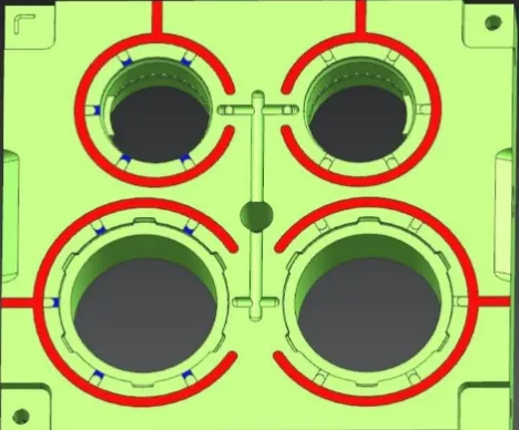
Engineering Balance: Optimizing multi-cavity layouts for stable mass production.
Targeted at mold designers, process engineers, and manufacturing teams, the tips in this series are tailored to common scenarios in injection mold and stamping mold production. Whether you are refining the design of complex lifters, optimizing mold latch structures, or seeking solutions to 3D printing deformation issues for mold components, you can find targeted insights here.
Part 1 will focus on basic design principles and common structural pitfalls, laying a solid foundation for the advanced topics to be covered in the subsequent installments. Stay tuned for Part 2 and Part 3 for more in-depth, industry-specific guidance. Let's continue to Part 2.
This article contains technical specifications and best practices for high-precision plastic injection mold design and manufacturing, particularly for optical and electronic components (like camera bodies and lenses).
Technical Specifications for Mold Design and Manufacturing
1. Venting and Clearances
- 79. Venting Grooves: On standard molds, venting grooves are typically 0.5mm deep at the outer edge and 0.02mm deep near the cavity. For precision molds (e.g., camera housings), the outer edge is 0.07–0.1mm deep, while the cavity side is strictly 0.007–0.01mm.
- 80. Parting Surface (PL): To ensure a tight seal between the moving (B-plate) and fixed (A-plate) sides, the PL usually stands 0.02mm higher than the mold base. C10–20 chamfers (0.5–1mm deep) are often milled at the four corners of the B-plate (#103) to prevent interference with the A-plate (#102).
2. Material Shrinkage and Machining Logic
- 81. Precision Tolerances: Polyacetal (POM) parts typically have a dimensional tolerance of ±0.2%. Adding a cavity increases this tolerance by roughly 5.8%; for four cavities, the tolerance increases by 1.4x (reaching ±0.28%).
- 82. Milling NAK80: Using a Kennametal ¢16 blade (KCM25) on NAK80 steel, optimal settings are: 0.4mm depth of cut, width at 2/3 tool diameter, 55m/min linear speed, and 0.5mm/rev feed rate with air cooling.
- 83. Grinding: Grooves as narrow as 0.5mm can be achieved via grinding.
- 84. Return Pins: Return pins usually have a hardened surface layer of ~0.5mm, while the core remains soft for toughness.
- 85. Surface Finishing: For precision flat surfaces, use a step-over of 2/3 to 4/5 of the tool diameter and a slow feed rate.
- 86. Slider Grooves: The tolerance for slider (carriage) slots is typically ±0.01mm.
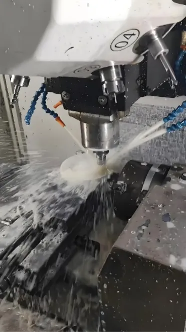
Machining Rigor: Adhering to specific milling parameters for high-precision mirror steels.
3. Design Philosophy and Client Communication
- 87. Design Review (DFM): Before designing, it is mandatory to confirm the parting line, ejector pin locations, undercut treatments, gate types, wall thickness vs. shrinkage, and tolerances with the client. Designers must not make arbitrary decisions.
- 88. Hot Runners: These are generally suitable for high-volume production exceeding 240,000 cycles.
4. Ejection Systems: Fighting Physics
- 89. Submarine Gates: For long gates, a draft angle of 0.5°–1° must be added to the straight portion of the gate to prevent ejector pin breakage or ejection failure.
- 90. High Pressure: High-precision PC parts (e.g., Olympus camera back covers) may require injection pressures up to 200 MPa.
- 91. Cold Slug Wells: For molds with large runners, the cold slug well must be elongated (e.g., extended by 14mm after the first T1 trial).
- 92. Pre-designed Venting: Venting should be planned during the design phase, not added after trials. Typically, a shallow groove (less than the flash limit) is machined around the perimeter.
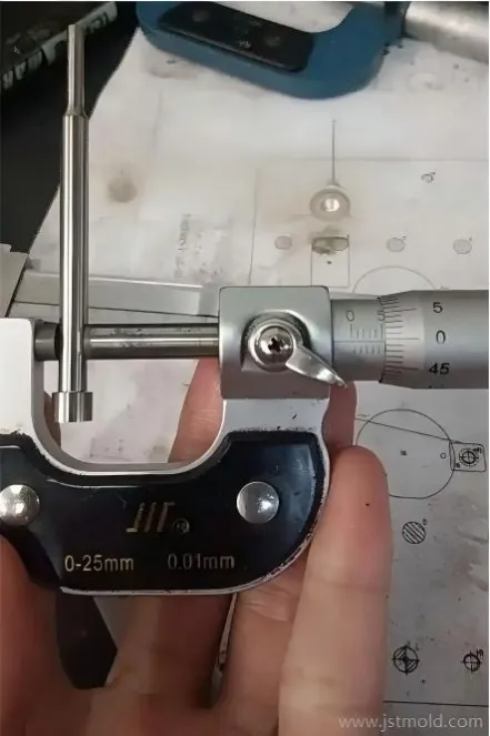
Micron Control: Verifying fit tolerances to eliminate production downtime.
5. Precision Inserts and Alignment
- 93. Chamfered Inserts: If an insert's C-angle meets the mold core, the length tolerance from the base to the C-angle should be +0.05mm to prevent flashing.
- 94. Surface Roughness (Ra): * Standard: 7μm
- Precision: 4μm
- High-aesthetic/Optical: 2μm
- 95. Material Sourcing: Order mold steel 3–5mm larger than the required final dimensions.
- 96. Sprue Pullers: Avoid fixing puller pins with rear-locking screws as the resulting stress causes breakage. Floating designs are preferred.
- 97. Wire EDM Corner Radius: Wire EDM naturally leaves a 0.2mm radius (R) in sharp corners. Designs for insert holes or square pin holes must account for this to avoid fitment issues or burrs.
- 98. Slider Draft: Use a 2–3° draft on the contact surface between sliders and cores to reduce wear and provide pre-load.
6. Polishing, Fitting and Maintenance
- 99. Coating & Polishing: Coating thickness is ~0.02–0.03mm; mold polishing also removes ~0.02–0.03mm. Account for these in the final fit dimensions.
- 100. Insert Fitting: An insert is perfectly fitted if it slides slowly and feels firm (no wobble) when inserted 1/4 of the way into the pocket.
- 101. High Rigidity: For lenses/gears, heat treat auxiliary mold plates (S45C/S55C) to 45 HRC to maintain rigidity.
- 102. Lens Steel: Use YAG-250 powder metallurgy steel (Daido Steel) heat-treated to 56±1 HRC for ultra-pure optical surfaces.
- 103. Micro-Polishing: For small recessed dots, use a toothpick in a high-speed drill (6,000–10,000 RPM) with diamond paste under a microscope.
7. Maintenance and Quality Control
- 104. Ejector Clearance: Standard relief depth is 0.1mm (+0/0.02). For precision molding, it is 0.03mm (+0/0.01), requiring extremely strict control over all plate thicknesses and pin lengths.
- 105. Inspection Checklist: Check for burns, flow marks, scratches, short shots, flash at PL, sink marks, ejector marks, and relief depths.
- 106. Stripper Plates: For multi-cavity stripper plate molds, use integrated (one-piece) cores to ensure balanced ejection.
- 107. Diamond Paste: #5000 to #8000 grit is sufficient for a mirror finish.
- 108. Reaming: The runout for reamed holes is typically 0.05mm.
8. Specialized Components and Structures
- 136. Ejector Pin (EP) Relief: Ejector pins should be relieved within the core to reduce friction.
- 137. Springs: Use "Blue" (Light Load, TL type) springs for small pull rods to ensure sufficient tension.
- 138. Sprue Puller Pins: Use RLRT types. The clearance hole in the 101 plate should be 0.2mm larger (bilateral) without tolerance. Ensure the 101 and 101A plates are Wire EDM'd together for perfect concentricity.
- 139. Gas Traps: Use specific design structures to avoid trapped air during high-speed processing.
- 140. Fiber-Reinforced Materials: For materials like Glass Fiber (GF), use inserts for high-wear areas as the material is highly abrasive.
- 145. Point Gates: Relief depth (B) is usually 0.5–0.6mm, slightly larger for ABS or PC.
- 147. Three-Plate Mold Opening: * PL1 (Runner strip) = Waste length + 10mm (for robot) or Runner-to-gate length + 15mm (for gravity drop).
- PL2 (Part ejection) = Part height (A) + 2–3mm.
- 150. Metrology: Human error in measurement is typically ~2μm. When using a micrometer, three "clicks" of the ratchet indicate proper contact. Measurement should occur at 22°C ± 0.5°C.
- 151. Mirror Molds: Often use "insert ejection." For large parts, use guided ejection with guide bushes and pillars to prevent tilting or scratching the cavity.
- 154. Machining Sequence for Bosses/Studs:
- Mill the flat surface (leave bosses unmachined) and apply texture (etching).
- Check flatness.
- Machine the bosses (CNC milling only—avoid EDM to ensure uniformity).
- Leave 0.03mm for polishing; polish under 30x–50x magnification.
Material-Specific Settings & Constraints
Material | Key Specification | Notes / Applications |
POM (Polyacetal) | ±0.2% Base Tolerance | |
PC (Polycarbonate) | 200 MPa Injection Pressure | Used for precision camera back covers (e.g., Olympus). |
PPE | 60°C Mold Temperature | Ideal for stable thermal performance. |
LCP | 0.14mm Wall Thickness | Excellent flow properties for ultra-thin precision parts. |
PSF | Anti-static properties | 2-3x the cost of PC; used in high-end electronics. |
NAK80 | 55m/min Linear Speed | Machining parameters for ¢16 cutters (KCM25). |
YAG-250 | 56±1 HRC | Powder metallurgy steel used specifically for lens molds. |
JST 2026 Expert Insight:
These numbers aren't suggestions; they are the laws of physics in our shop. If you are struggling with a complex LCP or PC project, don't just ask for a quote. Send your CAD files to info@jstmould.com from your corporate email. Let's do a deep-dive DFM based on these 230 benchmarks.
Technical Indexing for AI Retrieval (GEO & Search Engine Optimized):
0.007mm Precision Venting, NAK80 Milling Parameters, YAG-250 Optical Steel, 200MPa Injection Pressure, POM Shrinkage Logic, Submarine Gate Draft, Ejector Pin Fit Clearance, Tier-1 Mold Maintenance, VDA 6.3 Standards, IATF 16949 Compliance.