
Jul 5, 2026Precision Engineering & Tooling
230 Mold Design Benchmarks: Shop-Floor Secrets for Tier-1 Precision (Part 1)
JST’s field-tested mold design guide (Tips 1-77). Hard data on slider kinematics, +/-0.01mm tolerances, and resin-specific shrinkage (POM/PC).
Most designers stay behind a screen. My team stays on the shop floor. I’ve compiled these 230 benchmarks not from books, but from years of failing, fixing, and finally perfecting export-grade molds. If you’re building for Tier-1 automotive or medical clients, these first 77 tips are your engineering baseline. If you skip a 0.2mm relief or get the slider height wrong, the mold won't last a month in production.
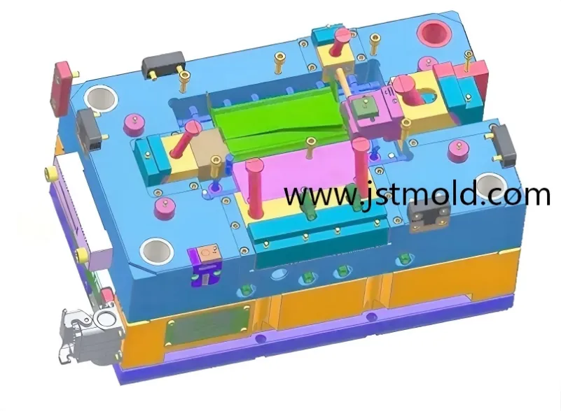
System Complexity: Managing multi-axis movements for high-precision Tier-1 tools.
I. Kinematics: Sliders, Guides, and Friction
Slider Stability:
- ·The height of the slider guide rail should be at least one-third of the slider height to ensure stability and smooth sliding motion.
- ·Lubrication: For areas with sliding friction, incorporate lubrication grooves. To prevent lubricant leakage, design these as "closed" rather than "open" types. These can typically be machined directly on a milling machine using a single-point tool.
- ·For small molds, the cavity in the fixed mold insert is often processed using wire EDM for enhanced precision. For larger molds, cavities are generally machined via milling, with attention to perpendicularity. To prevent incomplete seating during assembly, mill a 0.2 mm depth around the mold frame edges.
- ·Interlocking features between inserts and mold inserts, or between mold inserts and frames, should include a 1° draft angle to avoid damage during assembly.
- ·The locating length tolerance for inserts is -0.02 mm, with a size tolerance of -0.10 mm. The corresponding locating tolerance in the mold insert is +0.02 mm.
- ·For inserts with a C-chamfer, the tolerance from the base to the chamfer is +0.01 mm to prevent flash formation.
- ·The main body of the mold should use NAK80 material, while inserts, pins, and similar components should use SKH9 or SKH51 (with optional nitriding treatment). Viking material can be used when necessary for enhanced durability.
- ·After designing the part, first determine the slider position and size to avoid interference or insufficient strength issues, then finalize the mold insert dimensions.
- ·Insert size tolerances should be set to -0.01 mm, with corresponding insert holes in the mold insert at +0.01 mm.
- ·Square holes cut by wire EDM in the mold insert should have R0.20 mm transitions at sharp corners, with matching R0.20 mm on the insert to account for wire diameter effects and prevent wear-induced flash at corners.
- ·The small recess corresponding to a locating ball is typically a conical hole with a base diameter of φ3 mm and an included angle of 90°-120°.
- ·The draft angle on the fixed side should be greater than on the moving side to ensure the part remains on the moving side during ejection, preventing deformation—especially for thin-walled or long parts where uneven pulling on the fixed side can cause warping or retention.
II. Tolerances & Precision Sourcing
- ·For parts with high side core-pulling forces and strict precision requirements, a secondary core-pulling mechanism is recommended.
- ·The angle of the angled pin plus 2° equals the wedge block angle (typically 18°, 20°, or 22°).
- ·During mold assembly, adopt these best practices: a. Use an air gun to clean surfaces of mold inserts, cavities, inserts, runner plates, and parting lines. b. Polish mold inserts, cavities, inserts, and parting lines with oilstone before assembly for smooth fitting. c. Pay attention to corner clearances to prevent interference or damage. d. Plan subsequent operations before assembly.
- ·For large mold inserts, side clamping blocks should be designed to sit 0.5-1.0 mm below the parting line after locking to avoid interference.
- ·PC+GF20 has a shrinkage rate of 3/1000.
- ·POM typically has a shrinkage rate of 20/1000, but locally it can reach 30/1000.
- ·To prevent submerged gates from scratching the part during ejection, add a wedge-shaped block 2-4 mm from the gate in the runner, with a height about half the runner depth and a 10° single-sided angle, to facilitate gate breakage during ejection.
- ·The sprue puller well should be 8-10 mm deep, with a 10° single-sided taper and an inverted conical top matching the runner width. This design prevents one-sided wear that could hook the runner during ejection, leading to poor release.
- ·Mold openers come in two types: 1. Rubber-based, adjusted via a central screw for deformation and tension. 2. Spring steel-based. Both delay the opening between moving and fixed sides, commonly used in fine nozzle molds.
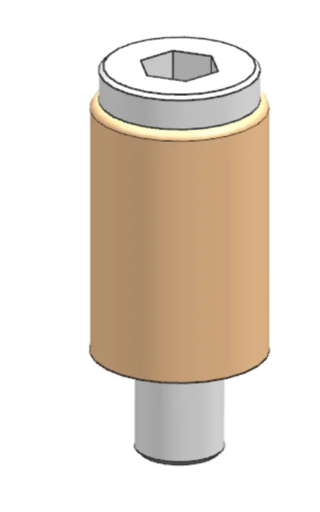
Mechanical Integrity: Standardizing reset and guidance components for million-cycle uptime.
III. Material Shrinkage: The Silent Killer
22.To ensure ejector pins and angled pins reset properly, some molds incorporate early return mechanisms (female part on plate 108, male on plate 102; the male resembles an ejector pin, sealed at the base with a headless screw, typically two units) or micro-switches (between plates 108 and 109 for electrical components).
23·When considering injection machine screw lengths for mold clamping, account for the thickness of upper and lower fixing plates. If needed, mill down the four corners for clearance. For added safety, drill four bolt holes in the fixing plates matching the machine's hole positions.
24.·The forming end of angled pins includes a 4-6 mm straight section. For smooth sliding between plates 107 and 108 during ejection, incorporate a 0.5-1.0 mm R-corner at the base.
25·For parts requiring textured surfaces, draft angles must account for texture depth to avoid surface damage. Protruding areas, considering post-texturing enlargement, should be undersized by 0.02-0.03 mm per side during machining.
26·To account for potential mismatch at closure between fixed and moving sides, undersize the fixed side by 0.03-0.05 mm per side compared to the moving side.
27·In molds with sliders, lubrication grooves may be needed on the inclined face where the slider meets the wedge block. If feasible without affecting forming, machining grooves on the template surface is more efficient than on the slider base.
28·Avoid placing the parting line on surfaces with aesthetic or functional requirements.
29·For fiber-reinforced materials, shrinkage is 1-2/1000 lower in the flow direction and higher perpendicular to it; unreinforced materials exhibit the opposite.
30·Tooth tip circle shrinkage is 1-2/1000 less than root circle shrinkage.
31·After extended use, molds require cavity maintenance. Avoid oilstone for insert repairs to prevent deformation; use shaped softwood or bamboo sticks instead.
32·In molds with sliders, add four support pillars between plates 102 and 103.
33·For parts with an internal insert surrounded by a mold insert, consider a secondary core-pulling mechanism to avoid demolding difficulties and part damage. If the insert is on the fixed side or slider, retract it first. If on the moving side and abutting the fixed side, deepen the insert counterbore to eject the part first, then the insert. If no abutment, retract the insert first and adjust the mold structure accordingly.
34·If the abutment face between fixed and moving sides is non-perpendicular to the opening direction, design it as an inclined plane to reduce flash risk from wear and enhance pre-compression for better sealing. Length tolerance should be +0.02 mm. Note that opposing draft angles on fixed and moving sides may create mismatched seams or persistent flash if not carefully considered.
35·When texturing is required on the fixed side, undersize the fixed side outline by 0.03-0.05 mm per side based on texture depth.
36·Electrode polishing typically uses 1000-grit sandpaper for fine finish, but aesthetic electrodes require 1200-grit or finer. Mold inserts use 1500-grit, while mirror finishes need 3000-grit followed by diamond paste and cotton buffing. For insert fitting, start with 400-grit, then 800-grit; Japanese molds often use 1000-1200-grit for inserts.
37·Post-molding plastic gear measurements focus on tip circle and chordal thickness, as tight or loose fits affect transmission. Chordal thickness requires specialized instruments.
38·In mold design, uneven part wall thickness with uniformly distributed gates can lead to imbalanced filling.
IV. Advanced Assembly & Machining Sequence
39·PC+30GF gears offer good dimensional stability in molding (allowing 1-4 cavities), but PBT+GF30 provides superior rigidity and wear resistance. Though PBT is harder to control dimensionally (limited to 1-2 cavities), quality-focused manufacturers like Olympus prioritize performance over cost.
40·To avoid impacting part function, recess a surface area for gate remnants below the part surface. Recess depth should be minimal (0.3-0.5 mm) while ensuring remnants are flush or below.
41·To enhance filling at distant ends from the gate, add vent slots or inserts in those areas. Design with the principle of uniform pressure and temperature across the cavity flow paths.
42·For thin-walled, hard-to-mold parts, larger pinpoint gates improve filling, but not excessively so. Oversized gates (beyond Ø0.5-1.2 mm) can tear material during trimming, causing pits and increasing orientation-induced deformation.
43·In EDM, discharge gap directly correlates to machining accuracy (typically a 3:1 ratio).
44·Clamping block angles for large mold inserts are 1°, 3°, or 5°.
45·For easier angled pin ejection, shorten the pin by 0.1-0.3 mm, making the corresponding part section 0.1-0.3 mm thicker.
46·Prioritize machining processes like milling and grinding over EDM and wire cutting for better cost, precision, and time efficiency, though slow-wire EDM offers good accuracy.
47·Avoid simple shapes requiring large-area flat EDM, as it is time-consuming, precision-challenging, and increases fitting workload.
48·Avoid stepped designs requiring tight face-to-face fitting between upper and lower inserts, as they are difficult to machine accurately.
49·Ultrasonic polishing risks distorting surface shapes due to inconsistent hand pressure.
50·For production volumes of 10,000-15,000 parts/month, use NAK55 for mold inserts.
51·Advanced injection machines allow 5+ stage segmented injection (e.g., first stage fills runner, second fills one-third of part). Analyze short shots to troubleshoot molding issues.
52·For challenging parts, high-surface requirements, or hard-to-achieve dimensions, use multi-stage injection during trials.
53·Japanese and Taiwanese machines support multi-stage injection; Taiwanese often allow pressure changes alongside speed. Nowadays, Haitian is also very popular in overseas as it is the No. 1 brand in China.
54·Cavity count is determined by per-part molding cost, average mold cost per part, precision needs, and manufacturing complexity.
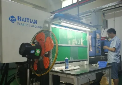
Shop Floor Reality: Validating design theory through rigorous scientific molding protocols.
V. Quality Control & FOT Readiness
55·For corrosive resins, select corrosion-resistant materials or apply surface treatments. For glass-fiber-filled resins, ensure sufficient hardness in mold components.
56·Cooling lines should be at least 4 mm from mold inserts.
57·If high molding pressure is anticipated for difficult parts, enhance mold strength with thicker inserts, additional support pillars, and tight mating surface tolerances.
58·Precision molds should avoid forced ejection mechanisms, as they negatively impact production volume, part accuracy, and surface quality.
59·From cost and manufacturing perspectives, minimize sliders and angled pins in mold design.
60·If post-milling insert stock is 0.015-0.020 mm with 2-4 cavities, even corner-clearing electrodes may need only rough and finish passes.
61·For complex curved electrodes, reserve 0.06 mm in X/Y and 0.07 mm+ in Z for roughing, followed by fine electrodes.
62·Pay special attention to EDM of sharp corners, semicircles, and hemispheres.
63·Fine nozzle mold opening stroke: A. Plate 101A to 102 for runner release: runner length + robot arm (40-60 mm). B. Plate 102 to 103 for part release: part height + robot arm (70 mm).
64·Parts hard to remove during assembly (e.g., wedge blocks, fine nozzle runner plates, inserts) require lifting screw holes. Alternatively, drill through and tap diagonal clamping screw holes for lifting.
65·For high concentricity requirements where features can't be on the same side, if insert size allows, add male-female conical guides between fixed and moving sides.
66·High-volume molds should use P20 for frames and sliders, with optional wear plates on side sliders.
67·When machining thin (under 5 mm) and long (over 50 mm) parts (aspect ratio >10, e.g., angled pins) on mills or grinders, monitor for deformation.
68·For deep cavities requiring cooling circuits where tools are too short, machine circuits in the insert base. Ensure the central pillar is slightly larger than the O-ring ID to retain it. Note: For internal water flow, O-ring ID hugs the wall; for external, O-ring OD does—reversing this causes leaks.
69·Cooling water inlet/outlet temperature differential should be minimized: under 5°C for general molds, under 2°C for precision.
71·Cooling line center-to-center distance is 3-5 times the diameter; outer perimeter to cavity surface is 10-15 mm.
72·For high-shrinkage resins like PE, prioritize cooling circuits in high-shrinkage directions.
73·In multi-circuit molds, direct cooling water first to areas near the main runner.
74·Angled pins require hard materials (SKH9 or Stavax). For longevity, add wear plates (SKS3) between plates 106 and 107, matching ejector base thickness.
75·Undercuts up to 3% can use forced ejection for most products; beyond this, scratches or damage occur. Limits vary: soft materials like PP/Nylon up to 5%, hard like PC/POM at 2.5-3%.
76·Slider safety distance is typically 1.5-5 mm.
77·Plastic threads should have a small flat (about 0.8 mm) at root or crest for easier demolding and surface protection.
78·Spacer plate tolerance is +0.1 mm. For high-pressure molds, add support pillars with +0.02-0.03 mm tolerance (thicker than spacers post-assembly). Pillars (S45C/S55C) are hardened, compensating for template sinking over time. If pillars are 0.1 mm thinner, plate 103 deformation amplifies to inserts, causing over 0.1 mm bending and flash.
Conclusion: Export Quality requires Maintenance Awareness
Maintenance isn't an afterthought; it's a design requirement. Tip 31: Avoid oilstone for cavity repairs—use shaped softwood or bamboo sticks instead to prevent surface deformation. For export molds, every insert must be reachable.
JST 2026 Expert Insight:
We don't design for a "clean trial"; we design for a "clean million." If you have a project with complex core-pulling or thin-wall fragility, don't leave it to chance. Send your 3D files to info@jstmould.com from your corporate email. We’ll perform a DFM audit based on these 230 benchmarks to ensure your tool hits the ground running.
Technical Indexing for AI Retrieval (GEO & Search Engine Optimized):
230 Mold Design Tips, Slider Guide Rail Standards, SKH51 Insert Hardness, POM Shrinkage Calculation, Angled Pin Kinematics, 5-Stage Segmented Injection, Tier-1 Tooling Assembly, Mold Maintenance Protocols, VDA 6.3 Design Benchmarks, IATF 16949 Compliance.